Self Balancing Scooter: Unterschied zwischen den Versionen
K |
K |
||
| Zeile 1: | Zeile 1: | ||
{{Projekt | {{Projekt | ||
|projectname=Self Balancing Scooter | |projectname=Self Balancing Scooter | ||
| + | |kewords_de= | ||
| + | |kewords_en= | ||
| + | |kewords_es= | ||
|subcat=Projects | |subcat=Projects | ||
|Images={{ProjektImages | |Images={{ProjektImages | ||
Version vom 24. Februar 2019, 19:46 Uhr
|
|
Self Balancing Scooter Basic Data Category: Projects URL (first publication): http://members.optusnet.com.au/~a4x4kiwi/scooter/
Project status:
Technical documentation Maturity of the project:
no no
Other
Assembly instructions are editable: Bill of materials is editable: Design files are in original format: No Free redistribution is allowed licence: No
Project management
Open-o-meter: 0 Product category: Vehicles & Parts Contains original non-electronic hardware: Contains original electronic hardware: Contains original software: |
Inhaltsverzeichnis
- 1 Description
- 1.1 Building an Open Source Self Balancing Scooter
- 1.1.1 Malcolm Faed
- 1.1.2 Copyright: This document may only be reproduced with the author’s permission.
- 1.1.3 Introduction
- 1.1.4 Parts List
- 1.1.5 Chassis
- 1.1.6 Batteries
- 1.1.7 Motor Controller
- 1.1.8 Microprocessor
- 1.1.9 Sensors
- 1.1.10 Software
- 1.1.11 Balancing
- 1.1.12 Turning
- 1.1.13 Measuring the platform angle
- 1.1.14 Over Speed
- 1.1.15 Misc.
- 1.1.16 Future Improvements
- 1.1.17 Links, credits and inspirational people.
- 1.1 Building an Open Source Self Balancing Scooter
- 2 + General Reviews
Description
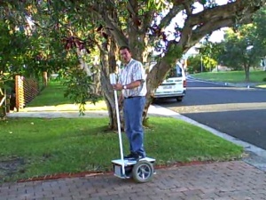
Building an Open Source Self Balancing Scooter
Malcolm Faed
Copyright: This document may only be reproduced with the author’s permission.
Introduction
In recent times, advanced electronic systems have become cheaper and cheaper and at the same time become more complex. The price of the components are now within reach of the hobbyist (e.g. Gyro and Accelerometer). This allows more complex systems to be built at relatively low cost. And most important these advanced technologies can be used by individuals and hobbyist where they were previously only available to more wealthy individuals and corporations.
This is also an excellent example of that brings together people from different continents and backgrounds to develop a common product.
This is a project I had contemplated for quite a few years since first seeing the on the Internet. I saw and had a ride on Geoffrey Bennett's home made scooter at the in 2007 in Sydney. he also offered the source code on his web site which was going to be the hardest part for me.
This project marries several of my passions, Electronics, Mechanics, Control Systems and Software.
Obligatory warning. Build this at your own risk. If you injure yourself or any one else its not my fault.
Parts List
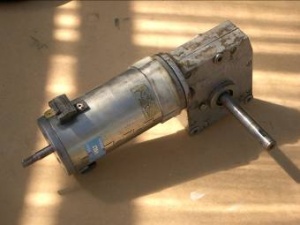
- Wheels with motors and reduction gearboxes - Electric Wheelchair - AUD$100
- 12mm Plywood to stand on and to hold the electronics - Free
- Batteries (3 x 12 volts) - Free with Wheelchair
- PWM motor controller - Locked Anti-phase for 2 motors - AUD$280
- Sensors - Accelerometer and Gyro - USD$114.95
- CPU - Atmel ATMega16 - AUD$43.76
- RC Joystick
- Misc cable and connectors.
Total ~ AUD$550
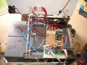
Chassis
- (Russell Cragg)
- Old electric wheelchair, cut chassis with grinder cutting wheel to suit
- Has 2x 24v motors already conveniently attached.
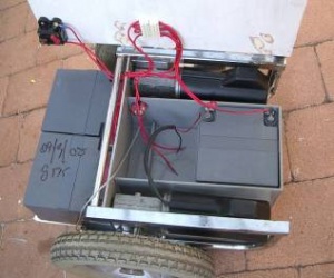
Batteries
- Conveniently from old electric wheelchair
- 36 volts total
- 3 x 24ah, 12volt SLA batteries.
- Charged in parallel, run in series.
- 60A circuit breaker doubles as a switch
- Position the batteries in such a way that the scooter is naturally balanced when unpowered.
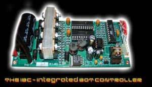
Motor Controller
- IBC From RoboWars.
- Two x 50Amp MOSFET controllers
- Replaced micro with Atmel ATtiny2313 and firmware to give locked anti phase control instead of default RC PWM inout ()
- Low dropout switching regulator
- Regenerative braking (inherent from locked anti phase motor control)
- Australian design and open source
Microprocessor
- Atmel ATMega16
- 8 bit
- 16k Flash
- 8MHz Clock
- 512 Bytes EEPROM
- JTAG
- ISP
- 3 Timer - Counters
- 8 channel 10 bit a-d
- Hardware USART
- 32 IO lines
- Many other features
- Development in AVR-GCC
- Prototype board from
Sensors
Gyro and Accelerometer fromWhich way is up?
How fast am I tipping?
Current Sensor - hall effect device and iron core.
Software
- Developed with AVR-GCC
- Reads the analogue inputs
- Drive the motors
- Read from RC receiver
- Write and read the serial port for logging and tuning
Balancing
- If the robot is leaning, drive the wheels in the direction of the lean
- f you lean more, go faster
- This is a control systems problem:
- input variable is the platform angle
- output variable is motor speed (PWM). 50% duty cycle is stationary.
- by controlling the motor speed and direction, keep the platform horizontal
- Attempt to keep the platform angle zero
- output = Kp x input + Kd x input’ + Ki x input dt
- Proportional — if you lean more, go faster
- Derivative — if you lean quickly, go faster
- Integral — if you’re still leaning, go faster
Turning
- Joystick for input (also RC)
- Speed up one wheel one wheel
- Slow down the other wheel.
- Turn faster when stationary. Turn slower when traveling.
- Accelerometer and gyro must be in center between the wheels otherwise it senses turning as tipping.
Measuring the platform angle
- The Gyro input gives the angular rate but it drifts a lot
- The Accelerometer input gives the acceleration due to gravity and due to the scooter accelerating
- When the scooter is not accelerating, the inverse-sine of the accelerometer input gives us angle
- This isn’t very precise
- It is susceptible to vibration
- But it doesn’t drift
- How to combine them?
- The Gyro input averaged over time should be zero
- This lets the software adjust for drift
- We assume initial angle is given by the accelerometer
- Track angle changes with the gyro
- If the tracked angle is different to the angle from the accelerometer, track towards it slowly
- Subtract any acceleration force we apply to the motors from the accelerometer reading
- When moving, rely less on the accelerometer reading
- sin(x) ~ (for small x) This omits the need for Trigonometry in the software.
(Adapted from Geoffrey D Bennett presentation)
Over Speed
- At some point, the motors can’t go any faster
- Then you fall, because the wheels can’t keep up with you
- Solution: before that happens, “push back” on the rider by making the wheels go even faster
(Adapted from Geoffrey D Bennett presentation)
Misc.
- In the first few seconds of running, slowly ramp up to avoid lurching.
- Voltage Reference - ADXRS401 has a 2.5V precision output
- Used to measure regulator voltage and scale inputs appropriately
- Use a-d to measure battery voltage and scale outputs appropriately to compensate for discharging battery
- Tuning
- Uses Perl-GTK on Linux with graphical UI in Linux from Geoffrey Bennett.
- Tipped
- If the platform angle is “too large”, shut down
(Adapted from Geoffrey D Bennett presentation)
Future Improvements
- Better Heat sink for MOSFETs
- Over current monitoring (LED)
- Low battery voltage warning (LED)
- Detect when rider not present / Present and adjust balance parameters accordingly
- If the kill or dead-man switch is tripped, shut down
Links, credits and inspirational people.
This project would not have been possible without the assistance of the following people.
Geoffrey D Bennett - for the source code and tuning software
Trevor Blackwell