OPenT: Unterschied zwischen den Versionen
Aus Open Source Ecology (OSE) Germany - Entwicklungsplattform
(Die Seite wurde neu angelegt: „{{Projekt |projectname=OPenT |subcat=Diagnosegeräte |Images={{ProjektImages |projectimage=138.1.png }}{{ProjektImages |projectimage=138.2.png }}{{ProjektImage…“) |
K |
||
| Zeile 1: | Zeile 1: | ||
{{Projekt | {{Projekt | ||
|projectname=OPenT | |projectname=OPenT | ||
| − | |subcat= | + | |subcat=Projects |
|Images={{ProjektImages | |Images={{ProjektImages | ||
|projectimage=138.1.png | |projectimage=138.1.png | ||
Version vom 31. Januar 2019, 05:38 Uhr
|
|
OPenT Basic Data Category: Projects URL (first publication): https://sites.google.com/site/openspinmicroscopy/home/opt
Project status:
Technical documentation Maturity of the project:
no no
Other
Assembly instructions are editable: Bill of materials is editable: Design files are in original format: No Free redistribution is allowed licence: No
Project management
Open-o-meter: 0 Product category: Business & Industrial Contains original non-electronic hardware: Contains original electronic hardware: Contains original software: |
Description
OPenT
A full OpenSpin setup allows acquisition of both LightSheet and optical tomography (aka OPT) datasets. However, if you are only interested in optical tomography an OPenT is much simpler to assemble and operate. Light-sheet performs optimally with magnifications ~10-20x and with samples up to 1mm. OPenT is better suited for samples which need low magnification lenses (<4x) and samples a few mm or even cm. A simple OPenT scanner can be built in less than 1day, with the possibility of operating with transmitted light (a diffused while light source standing behind the sample) + 1 channel fluorescence emission mode (blue (LED) incident light & green fluorescence detected by the camera). This very basic OPenT did not include shutter or filter wheels, but is sufficient for acquired high-quality datasets (see for example the site)
NEW
For samples labelled with two (or more) fluorescent dyes, or light-sensitive fluorophores, we have recently redesigned the OPenT to include the necessary for illumination with multiple LEDs + shutters + filter-wheels, while keeping the system simple and small footprint; we also prepared a new plugin (OPenT spin off) with only the functions for OPenT, and a macro to pre-process the OPenT datasets for filtered back-projection reconstruction (eg with the freely available software). This makes it much simper for those interested only in a high-end OPenT system; we hav also optimized the hardware control and acquisition times are now ~5x faster. We will soon be posting more information
For mode details on parts, assembly, new plugin or macro please contact
(the following instructions and diagrams relate to the version we published before (please cite us))
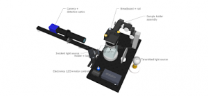
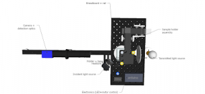
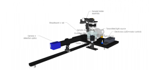
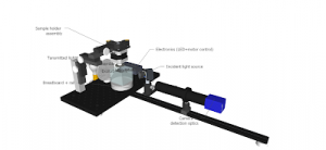
Diagrams
Details on the parts list can be found
All parts should be assembled onto the breadboard according to the following diagrams:
Details on the parts list can be found
All parts should be assembled onto the breadboard according to the following diagrams:
OPT assembly
OpenSPIN-OPT
DIY OPenT sample chamber (cuvette)
Start with a common glass slide (75mm x 25mm x 1mm) and using a diamond knife cut it into 3x25mm squares. Buff the sharp edges to prevent accidental injuries during assembly and use
Using another glass slide, use it as the base of the chamber and then glue the three walls in the center as in the figure sequence below (cyanocrylate glues ARE NOT stable enough once exposed to BABB so avoid). We have seen inconsistent resistance to BABB from brand to brand of cyanocrylates, epoxy and silicone glue. Try The "professional" grande Locktite cyanocrylate seems to work well.
Using another glass slide, use it as the base of the chamber and then glue the three walls in the center as in the figure sequence below (cyanocrylate glues ARE NOT stable enough once exposed to BABB so avoid). We have seen inconsistent resistance to BABB from brand to brand of cyanocrylates, epoxy and silicone glue. Try The "professional" grande Locktite cyanocrylate seems to work well.
We had more luck lately with RTV silione glues (especially the "neutral" ones, not those that smell like vinegar) for cuvete assembly. You may find it at auto-stores, ask for a silicone glue for the engine cooling system.
Finally add the front "wall" using a cover glass (22x22x0,17mm). This thinner wall of glass will face the camera+lens. The larger base (75mm) facilitates handling of the cuvette and avoid fingerprinting the lateral walls. Be extremely careful with the "front" window, as the coverglass is fragile and cracking it could mean leaking BABB and possibly ruining the breadboard or other components. Larger cuvettes can be similarly assembled starting from large microscope slides/cover glass available from microscope suppliers (often expensive, though). During imaging, we maintain the cuvettes inside a large glass Petri-dish covered at the bottom with absorbing tissue, to contain any accidental spillage of immersion medium. The commercial "cells" (eg Helma) are expensive but highly durable and resist all solvents. They have sizes that are not available in the catalog ask
Detail of sample chamber front, facing towards camera lens:
click on the images to enlarge
Detail of incident light assembly (LED + optics) facing sample chamber;
Positioning the stage and camera:
The XYZ stage holder and kinematic mount attached to the motor facilitate positioning, centering and leveling of the motor axis in relation to the camera center-view. This is ABSOLUTELY ESSENTIAL for proper image reconstruction, as even slight deviations of just a few decimal degrees will case major aberrations in the final reconstruction. Start with a 2-4cm flat cap screw connected to the center of the magnet, dip it into sample chamber with camera turned on and adjust XYZ and camera to get the screw in the field-of-view (FOV). Leveling of the axis can be facilitated also using a "3 axis bubble level", such as those sold in photography stores (eg ), glued to a 3cm diameter metal washer and connected to the magnet (be careful, BABB will ruin the plastic).
The XYZ stage holder and kinematic mount attached to the motor facilitate positioning, centering and leveling of the motor axis in relation to the camera center-view. This is ABSOLUTELY ESSENTIAL for proper image reconstruction, as even slight deviations of just a few decimal degrees will case major aberrations in the final reconstruction. Start with a 2-4cm flat cap screw connected to the center of the magnet, dip it into sample chamber with camera turned on and adjust XYZ and camera to get the screw in the field-of-view (FOV). Leveling of the axis can be facilitated also using a "3 axis bubble level", such as those sold in photography stores (eg ), glued to a 3cm diameter metal washer and connected to the magnet (be careful, BABB will ruin the plastic).
The camera should also be leveled, and the front wall of the sample chamber (cuvette) should be perfectly parallel to the objective front. Even after these adjustments, minor corrections may be necessary a posteriori as explained in the Supplementary Materials. When the specimen is longer than wider (eg an embryo) the camera should be rotated 90º to fill the camera chip (in the screen, the embryo will be rotating horizontally; before back-projection reconstruction, images need to be rotated again so that the axis of rotation is vertical).
Adjusting the illumination:
Transmitted light source: center the light-bulb with the middle of the back wall of the cuvette and ensure that the FOV is evenly illuminated in the image. To hold the diffuser glass upright, glue it to a metal plate. If FOV is uneven, acquire an image without sample and use it later to subtract the background.
Incident light source (fluorescence): the source should be placed as close to the sample as possible ensuring that it is fully illuminated. Try to illuminate from an angle as close to the detection axis as possible (without blocking the field view) and avoid the cuvette corners. Larger samples will require moving the LED source away as possible to ensure full illumination and will require longer exposure times.
Note: There are in-axis options commercially available for incident light; it requires collimation of the LED light and additional optics which are quite expensive, and in our experience the light losses are considerable in some cases. All images we have produced or published so far were done with off-axis illumination as described above, for samples from a few mm to cm thick.
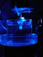
(detail of sample block (with specimen embedded) submerged in the cuvette filled with BABB and illuminated with blue incident light)
Subpages (1):