Open ECG
|
|
Open ECG Basic Data Category: Diagnosegeräte URL (first publication): http://www.gammacardiosoft.it/openecg/getting_started.htm
Project status:
Technical documentation Maturity of the project:
no no
Other
Assembly instructions are editable: Bill of materials is editable: Design files are in original format: No Free redistribution is allowed licence: No
Project management
Open-o-meter: 0 Product category: Business & Industrial Contains original non-electronic hardware: Contains original electronic hardware: Contains original software: |
Description
A John Wiley & Sons, Ltd., Publication
Build yourself
Build yourself the ECG
Gamma Cardio Cg is the first open source certified diagnostic electrocardiograph
with all the design disclosed in a book from the concept stage to the certification.
It is intended for anyone interested in
studying, and developing medical instruments.
The textbook
Engineering resources
Medical Resources
This page shows how to build the Gamma Cardio CG ECG that is marketed and certified in the Europe Union. The specifications of the product are . The internal Gamma Cardio CG board looks as follows. Note the insulated (CF applied) floating part that is in contact to the patient and the non-insulated part on the right side.
Before downloading files, remember that: YOU CANNOT USE ANY DEVICE ON HUMANS UNLESS CERTIFIED UNDER APPLICABLE REGULATIONS.
Gamma Cardio Soft can in no way be deemed liable for any damage through the use of the information contained in the book and in this website. By downloading these files you agree to the terms contained in the
Download first the , and the (Orcad .opj, .dsn files, unzip file in a directory and open .opj file) to understand how the board works. Understanding circuits is not difficult; in any case a detailed explanation is contained in the chapter 5 and of the textbook "".
You can order faster via if you are a registered user.
Go to “My Digi-Key>BOM Manager>Text File Import”, then copy the green area of into the import windows. Components cost around 126 $ for one board to 75$/board when buying components for 40 boards (2013 November prices shipment not included).
Download or (open file “gammacardiocg_30_2.gvp” in the zip file).There is a minimal bug on PCB (Printed Circuit Board). Special mention on this site for who discovers the bug first. (Special mention to Richard Berger who found the error: R49 pin is unconnected in the Gerber file, it must be connected to VCC). It is a 4 layer PCB that can be provided on line by many manufacturers.
Smaller components are 0603 resistors and 32-LQFP chip. All Smd components can then be even soldered manually. See that can be found on line. Otherwise they have to assembled by automatic pick and place machines, but this implies a minimum number of boards to be assembled. The J1,J2,J3, U4, are THT components that have to be soldered manually. As indicated in the following figure. If not available in SMD, ISO1 e ISO 2 in THT package may be soldered as follows
For capacitor C26, first two strip pins have to be soldered and then capacitor has to be soldered as in the following figure. Place a small strip of double-sided tape on the PCB, place the capacitor (The capacitor has no polarity, and then the direction is indifferent) and solder with a proper amount of solder paste to avoid disconnections of the capacitor due to mechanical shock.
The final assembled board should look like the one in the following photo.
Mounting the
To reduce artefacts from external noise, the board is shielded by an enclosure that is conductive in the external part and insulated in the internal part. The enclosure may be done by Mylar or copper. Insert the front mask that covers the ECG connector in the lower part of the box (see figure below). The lower part of the box is different from the top as it has the holes for the locking screws.
Create a shielding enclosure as in the . Fold the (copper or mylar) enclosure according to the guidelines given in the and lay the copper foil inside the lower part of the box.
Fold the flaps a and b to the internal so that the external conductive part may be in contact with the bottom of the PCB where the screws are positioned close to the ECG connector.
Place the PCB on the bottom of the box bottom and tighten the four screws securing the PCB on the box.
Check with the tester that the outer part of the conductive enclosure is in contact with the ground of the circuit. For the verification is sufficient to check the resistance between the conductive part of the enclosure and the grounding point shown in the following figure.
At the end, check with a tester that the screws of the connector are NOT in contact with ground.
Connect the Gamma Cardio CG board to a PC via USB and to the Gamma Cardio CG Programmer as shown in the following figure. The schematic can be downloaded . The required components are included in the . Caution the connector between the GC programmer and the Board must have the pin one close to the DC/DC converter (black square at the top of the following figure).
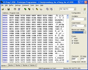
The board firmware can be downloaded by the ICProg programme connecting the the hardware as in the previous scheme.
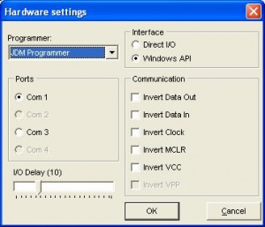
If you use NT, 2000, XP download and extract all the files in the same directory. Then, click on ‘Settings’ in the ICProg program and select the ‘Options’ window. Click on the ‘Misc‘ tab and “Enable NT/2000/XP Driver” as shown in the next figure. ICProg will then restart and work under NT, 2000, XP .
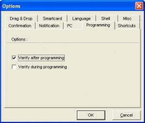
If you use a newer Windows version (Vista, Windows 7, … ) download and extract all into a directory. Uncheck “Enable NT/2000/XP Driver” in the Misc tab. Verify that the options have the values as in the following figures (menu Tools, Options and Hardware Settings menu settings)
Load the firmware file in the ICPROG program (Menu file load).
In the following figure there are the configurations to be set on the main form of ICPROG. In particular, note Oscillator = HS, code protect = CP ALL, Brown-out voltage = 4.2 and the fuses must be set PWRT and BODEN with PIC =PIC 16C773
At the end you should push the button "Program ALL" and wait for the message that communicate that programming has been performed successfully.
The ECG certified application program is now available in the . Refer to the for all the functions.
The application includes the software board test tool, the software board control tool, the software for simulations and evaluations. More specifically, the ECG Application Program can be run without hardware acquisition unit in demo mode. Configure the application in demo mode by clicking the Options button and then tick training mode.
In Demo mode the application works as it were a real patient connected to the ECG.
The ECG Application Program includes various design tools that can be accessed pushing shift and control and clicking on bottom right panel (sensitivity area).
The available tools are:
Tool | Tab name | Action |
Acquisition unit simulator, | Simulation mode | Configure the program as master, slave (i.e. board simulator), master slave on serial port or tcp,ip socket |
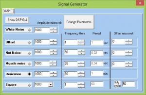
Signal-noise generator, ECG generator , | Simulation mode, Show generator | Generate synthetic or ECG signals with eventual noise |
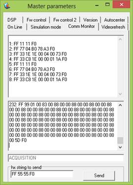
Traffic-protocol analyser | Comm Monitor | Show hex byte traffic (serial or TCP) between the application program and the acquisition board (also simulated) |
Video configuration (Scaling and zoom configuration) | DSP | Set vertical horizontal scaling and zoom |
Video Refresh analyser, | Videorefresh | Shoqs performance of real time visualization |
Microprocessor memory manager, | Fw control | Set and get microprocessor memory areas |
Microprocessor signal generator controller, | Fw control 2 | Activate and control signal generator inside the acquisition unit |
Hardware test tool | Fw control 2 Test form | Run built in test of the hardware acquisition unit |
For example, the signal generator create the sum of signals or derivations by ticking the associated box as shown below. Parameters like amplitude, frequency, offset can be changed as needed.
Through the acquisition unit simulator, various simulations are available. Master/slave connected connect the application to a virtual patient.
If Comm monitor activated option is ticked the data traffic can be shown real time in Comm Monitor tab. As shown below.
Additional resources
You can find additional engineering resources in the :
You can find additional medical Ecg resources in the :
t is Gamma Cardio CG
Gamma Cardio CG is a 12-lead diagnostic Ecg connected to the PC, certified and sold in the European market. The ECG is a medical instrument that records the electrical activity of the heart to diagnose specific diseases.
The product includes an hardware acquisition board, the associated firmware and a software program running on a PC. The Hardware (Cad, Bol, Gerber, …) is fully disclosed and open licensed under. The software and the firmware are released as executable with accessible experimentation tools (hardware control, signal processing, …) .
The product design know-how and the associated theory (bioinstrumentation, electronics, signal theory, software, and certification) is fully disclosed in a University textbook ("", Becchetti, Neri, Wiley).
The product is an high-end device due to
· Validated diagnostic performances
(compliance with Ansi Aami EC 11 standard)
· Maximum level of European certification
(suitable also for monitoring vital physiological parameters where variations result in immediate danger i.e. Class IIb)
· Maximum electrical isolation class
(suitable for direct cardiac application, defibrillation proof, i.e., class II CF double insulation compliant with standards EN 60601-1, EN 60601-2-25, EN 60601-1-2).
See for additional details. Any feedback and contribution are welcomed in the spirit of open hardware, mail at
Product description
12 lead Diagnostic PC-ECG (Electrocardiograph to be connected to the PC compliant to diagnostic requirements)
Market Approval
certification (certified according to European Medical Device Directive, marketed in European area)
Diagnostic performances
Compliant to
· ANSI AAMI EC 11(American National Standards Institute, Association for the Advancement of Medical Instrumentation)
· IEC/EN 60601-2-25
Resolution and acquisition
High resolution sequential acquisition and transmission of the 12 leads (one lead at time):
· Horizontal Resolution: 1200 samples/second
· Vertical resolution: 2.44μV/LSB .
Safety
Class II B certified according European Medical Device Directive (suitable for monitoring vital physiological parameters where variations result in immediate danger)
Electrical Isolation
· Double insulation
· Patient’s applied part CF type (i.e. may be also in direct conductive contact with the heart)
· Defibrillator proof only if used with the patient cable Fiab F 6726 R
Compliance to standard
IEC/EN 60601, IEC/EN 60601-1, IEC/EN 60601-2-25, IEC/EN 60601-1-2
Some contents included in this page are exclusively reserved to professionals in the medical and biomedical engineering area
+ General Reviews 
Public cad repository for non-electronic hardware
Public cad repository for electronic hardware
Public code repository
Assembly instructions
Bill of materials