?Cube: A Framework for 3D Printable Optomechanics
|
|
?Cube: A Framework for 3D Printable Optomechanics Basic Data Category: Projects URL (first publication): https://openhardware.metajnl.com/articles/10.5334/joh.8/
no no
Other
Design files are in original format: No Free redistribution is allowed licence: No
|
Inhaltsverzeichnis
Description
μCube: A Framework for 3D Printable Optomechanics
Abstract
Scientific instruments often require the integration of mechanics, electronics and optics. While the use of 3D printing techniques and commodity electronics has lowered the cost of instrumentation, the design and prototyping of optical components and light paths can be challenging and expensive. In recent years, attempts have been made to make optical devices more affordable using 3D printing as a method for production of optomechanical components. In this paper we present an assembly standard for the production of 3D printed optical devices. We describe a framework for parametric design of modular mounts, present two modules built using the framework, and demonstrate the potential for generalised design of modular optical devices following the μCube standard.
Metadata Overview
- Target group: Students and scientists in life sciences, physics, engineering.
- Replication: Components were produced and tested during peer review.
- See section “Build Details” for more detail.
(1) Overview
Introduction
Optical design and assembly is difficult compared to electronic and mechanical construction. One reason for this is the lack of affordable components and common engineering standards for optical assembly. Whereas it is possible to purchase lenses for a reasonable price, or scavenge them from old devices, the optomechanical components required to hold the lenses and other components in place are relatively expensive and available from few manufacturers. Further, buying and assembling optical systems requires expertise, which, together with high prices, creates a barrier for scientists and innovators.
The advent of 3D printing allows the design and manufacture of complex objects in small batches from various types of plastics with low production costs. The 3D printing scene has been expanding since 2010, and has made an impact in the field of optical design. Numerous open-source projects related to optics have been released in recent years. Among them are OpenFlexure microscopy stage (), FluoPi multi-fluorescent imaging station (), FlyPi microscope (), RamanPi spectrometer (), SLO camera (), Ultrascope telescope (). In addition, Formlabs have demonstrated that even lenses can be manufactured using 3D printers (). These projects are promising examples of the potential future of optical design, and call for establishment of design standards to promote sharing and further development.
In this paper we present µCube, a framework for 3D printable optomechanics, which offers a standard for design and assembly of optical devices. The framework exploits modular design, where individual optical modules can be attached through a common mechanical interface. The adopters of the framework can benefit from a broad selection of parts available in the µCube library, and can bring modularity to their designs. The µCube framework is parametric, which makes it possible to adjust generic design templates for specific needs and sizes of optical components.
Overall Implementation and Design
The design consists of two conceptual elements: the µCube and µFace. The former is a hollow cube, which provides a structural support and serves as an elementary module for optical device assembly. The latter is a customisable part, which fits into a µCube and provides housing for optical elements (see Figure ).
Each side of a µCube has an indentation for housing a µFace. The indentation allows each µFace to sit flush with the surface of the cube, and facilitates protection from incident light. Each corner of the indented recess features a cylindrical hole, which holds a threaded insert for attachment of a µFace. The diameter of the holes is slightly smaller than that of the threaded insert, so that the insert is held firmly, after being heated with a soldering iron and secured in the hole.
A µFace is square in shape, and features four notches at each side, which match those on a µCube. There are four tapered holes in each of the corners of a µFace, which coincide with positions of the threaded inserts and allow attachment of the µFace with four screws, as shown in Figure .
The µCube framework is implemented as an OpenSCAD library (). OpenSCAD is an open-source 3D CAD programming language that supports parametric definition of three dimensional models. More specifically, each model can be thought of as an output of a function, where user-defined parameters specify its dimensions.
The design of a µCube is based on a generic template with two parameters. The size parameter specifies the internal dimension of the µCube and prescribes the total space available for the internal optical components. In its default configuration the size parameter is equal to 40 mm. The second parameter, d, defines the dimensions of the µCube features. For example, the section of the µCube wireframe is a square with size 2d by 2d. The dependence of other features on parameter d is shown in Figure . By default, d is 7 mm, and the external size of a µCube is 68 mm.
The choice of parameter d largely depends on the size of the screws used for the assembly and can’t be smaller than the diameter of the threaded inserts. The size parameter can, in theory, take any positive value. However, the practical limits of size depend on the resolution and maximum build size of the 3D printer used for manufacturing. The smallest µCube we have successfully printed had parameter d set to 7 mm and size set to 15 mm, giving an external size of 43 mm.
Similar to µCube, µFace is a generic template, the size of which can be adjusted by varying the parameters size and d. In addition, µFace has a third parameter, which prescribes a size of a gap between an edge of a µFace and a frame of the µCube. The gap is necessary for frictionless removal and attachment of the µFaces to the body of a µCube. The details of the µFace parameters are presented in Figure .
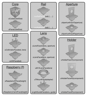
A µFace customised for a particular purpose is referred to as a part, whereas an assembled µCube is referred to as a module. At the time of publication, the µCube library contains 18 parts (see Figure ) and two modules (see Figure and Application section).
Library of parts. Currently there are 18 parametric parts in the µCube library, grouped into seven categories. Below each part is a corresponding OpenSCAD function, showing the main parameters. The Rail parts act as modifiers on any other µFace by adding rail attachments.
The screws used for the assembly are also defined parametrically using an instance of a Screw class. Therefore, it is possible to adjust the holes for the screws and screw inserts to match the available fasteners.
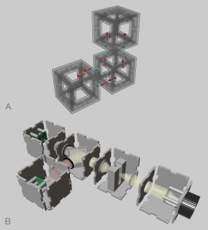
The modular nature of the framework allows joining several µCubes together into super-cube assemblies, thus making it possible to combine several modules into complex optical designs. Each side of a µCube features two additional screw inserts and two through holes. This allows joining any two µCubes together at any of the six sides using four screws in a bi-directional way (see Figure ). This configuration makes it possible to join up to six neighbours to each µCube, such that any structure in 3D space can be assembled. The elements are designed in such a way that a µCube can be attached to another, independent of whether it has a µFace attached at the interfacing side. This provides an option to house optical elements at the border between two µCubes.
Super-cube assembly. A) Joints in a three-cube assembly. Screws are highlighted in red; screw inserts are highlighted in cyan. B) A conceptual design of a µCube assembly including light source, detectors and light path modules.
Conceptually, every optical device constitutes of three main modules: light source, light path and light detector. The same categories can be applied to µCube modules. The µCameraCube and µLightCube, described in the Application section, are examples of a detector and a light source. They can be customised to work with various optical components either as independent units or as a part of a super-cube assembly. Further, we have designed generic holders for mirrors, lenses and filters that can be used for assembling light path components, hence allowing design of complete source – path – detector optical devices. For example, in Figure we show a design of a multi wavelength spectrophotometer, composed of two detectors, light source, sample holder and a light path splitter.
(2) Quality control
Safety
General safety measures should be taken when working with a 3D printer and soldering iron during the production and assembly.
Calibration
As described above, µFace template has a faceGap parameter that determines the distance between a µFace and a µCube necessary for a frictionless insertion and removal of parts. In our experience, a faceGap of 0.4 mm was an adequate value when printing µFaces on Ultimaker 2 or MakerBot Replicator Mini. However, calibration of the faceGap value may be required when using a different 3D printer. For this purpose, we recommend printing a set of µFaces with a faceGap from 0.1 to 0.5 mm and selecting the minimal value that allows frictionless insertion into and removal from a µCube. Note that the dimensions of a µCube do not depend on the faceGap parameter. Therefore, there is no need to reprint µCubes during calibration.
In order to make a calibration process faster, we have added a pair of calibration parts, µGapTestFace and µGapTestCube, which are the scaled down versions of a µFace and a single side of a µCube.
General testing
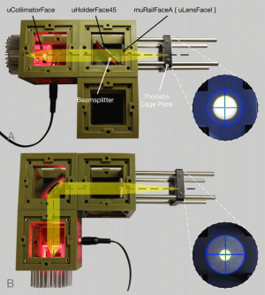
In order to test the degree of alignment between optical axes in a µCube assembly, we constructed a three-cube test device, composed of a light source, featuring a µColimatorFace; a cube holding a µHolderFace45 with a beam splitter; and an empty cube attached 90° to the main light path. See Figure for details.
Alignment testing. Photos of the alignment testing device and the images of the focused light beam on the paper screen for A) transmitted light and B) reflected light. µFaces are labeled in black, optical components in white. Blue circles and crosses represent the position of the aperture, green circles and crosses are fitted to the image of the light beam.
The collimated light, produced at the light source, can be focused by a lens on a screen, and the resultant image of the light spot can be used to evaluate the alignment of the optical axes. For this purpose, we attached a Thorlabs SM1-threaded standard cage plate to a modified µLensFaceI, featuring an adapter with four Thorlabs rods and a plano-convex lens. We then used this face to obtain images of the light beam at various positions on the test device by sliding the cage plate along the rods.
First, we ensured that the collimated light is aligned with the center of the light source cube by attaching the modified µLensFaceI directly to the light source cube opposite the µColimatorFace. Then, we attached the light source cube to the remaining optical system and obtained images of the light beam either after being transmitted through (Figure ) or reflected from (Figure ) the beam splitter.
We quantified the alignment of the light spot by taking a picture of the screen and calculating the distance between the centers of the circles fitted to the cage plate aperture and the image of the light spot. The resultant misalignment was ~0.14 mm for the transmitted light and ~0.44 mm for the reflected light. Given the total light path of ~195 mm, angles of the misalignment were ~0.04° for the transmitted light and ~0.13° for the reflected light.
(3) Application
Use case(s)
We used µCube framework to design a detector (µCameraCube) and a light source (µLightCube) module.
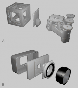
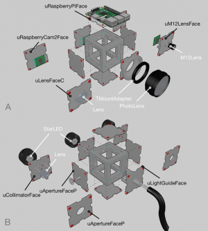
The µCameraCube, is a camera module, based on the Raspberry Pi and Raspberry Pi camera. It is composed of one µCube, three blank and three customised µFaces: µRaspberryCam2Face, for holding a Raspberry Pi camera module; µRaspberryPiFace, for holding a Raspberry Pi board; and a µFace for holding a lens. µCameraCube comes in three versions, which vary in the type of lens used. The lens can be either from a commercial photo camera, M12 CCTV camera lens or a thin lens. See Figure for details.
µCube Modules. A) Assembly of a µCameraCube. Left to right: thin lens version, photo lens version, M12 CCTV lens version. B) Assembly of a µLightCube. Left to right: collimator version, light guide version, point source version. Black arrows label parts; white arrows label components that serve as input parameters. Screws are highlighted in red; screw inserts are highlighted in cyan.
For attaching a commercial photo camera lens, a µTMountFace is used, which features a T-Mount adapter ring, obtained from a commercial T-Mount adapter. In the M12 CCTV camera lens version, both the lens and the Raspberry Pi Camera are held together by a single part.
The version of the assembly can be defined by a type parameter, which can be either ‘thin-lens’, ‘M12’ or ‘photo’. In addition, the distance of the lens and the Raspberry Pi Camera from the corresponding µFaces is calculated automatically based on the focal length of the lens and cameraOffset parameter. Therefore, during the design stage, it is only necessary to specify the focal length and size of the lens in order to generate the models ready for 3D printing.
µLightCube is a light source module, which is composed of one µCube, three blank µFaces and three customised µFaces: µLEDFace or µCollimatorFace for holding an LED with heat sink; µApertureFaceP with a hole for attaching a DC power socket; and either a µLightGuideFace or µApertureFaceP, which serve as a light output. See Figure for details.
Similar to µCameraCube, the µLightCube is provided in three versions. The point light source version uses a µLEDFace for holding an LED without any additional optics. In contrast, the collimator version uses a µCollimatorFace, which allows attachment of a collimating lens. Finally, a light guide version uses a µLightGuideFace designed for focusing collimated light onto the end of a fibre optics cable. The exact dimensions of the collimating and focusing lenses, as well as fibre optics cable and LED are provided as input parameters.
Reuse
Apart from offering a modular structure, µCube provides a standard for assembly of 3D printed devices, independent of whether they were designed using the µCube framework or not. An existing design can be extended to comply with the assembly standard by either directly adding a µCube compatible adapter or by introducing an adapter µFace. For example, we have repurposed an illumination arm of an OpenFlexure microscope to serve as an adapter face, and embedded a µCube adapter into the design of a 3D printed camera (). See Figure for details.
Examples of µCube adaptations. A) Extension of an OpenFlexure microscope with an adapter µFace, which serves as a support leg. B) µCube compatible adapter incorporated into the body of a SciFiCam allows using µFaces for lens attachment.
Commercially available kits, e.g. Optical Cage System by Thorlabs, offer comprehensive set of optomechanical components and allow manual adjustments at the build stage using a sliding rail system. Inspired by the Thorlabs design, we introduced two µFaces featuring rail clamps. The mµRailFaceA and mµRailFaceT act as modifiers that can be used to add rail attachments to any existing µFace. These µFaces not only give an opportunity to create low-cost alternatives to the commercial rail systems, but also allow to introduce custom-built 3D printed components into the existing systems, like those produced by Thorlabs.
(4) Build Details
Availability of materials and methods
3D models of all the parts presented in this paper were produced using OpenSCAD 2015.03 software. STL models were then imported into Cura 15.04.6 or MakerBot Desktop 3.10.0.1364 slicer software, and 3D printed using Ultimaker 2 or MakerBot Replicator Mini correspondingly.
For Ultimaker 2, 2.85 mm PLA filament was used with the following printing parameters: 0.1 mm slices, 100% infill, build plate adhesion set to ‘Brim’ and enabled supports for µFaces; 20% infill, build plate adhesion set to ‘Raft’ and disabled supports for µCubes.
For MakerBot Replicator Mini, 1.75 mm PLA filament was used with the following printing parameters: 0.2 mm slices, 100% infill, enabled raft and supports for µFaces; 20% infill, enabled raft and disabled supports for µCubes.
In general, we recommend printing µFaces with the external side up. However, when extrusions are present on the internal side, e.g. µLensFaceI in Figure , it is advised to print internal side up to eliminate the need for supports.
Once 3D printed, µCube elements were completed by embedding 36 M3 4 mm diameter, 4.78 mm depth screw inserts (six per side). The embedding was performed by heating the screw inserts with a soldering iron and pushing them into the pre-printed holes. µFaces were attached to the µCubes with M3 × 6 mm hex socket countersunk screws. The detailed assembly instructions are available at the DocuBricks portal.
Ease of build
Production and assembly of the µCubes and µFaces only requires a 3D printer and a soldering iron, no special skills are necessary. The design is implemented as a parametric template of three parameters, hence easy to modify.
Operating software and peripherals
Compilation of the STL files requires OpenSCAD 2015.03-3 and µCube library files available through GitHub.
Dependencies
Name: µCube at DocuBricks
Persistent identifier:
Licence: CERN Open Hardware License
Publisher: Mihails Delmans
Date published: 14/12/17
Name: µCube at GitHub
Identifier:
Licence: GNU General Public License v3.0
Date published: 24/08/16
(5) Discussion
Conclusions
Here we present µCube, a standard framework for 3D printable modular optomechanics. We have designed 18 parts, assembled two modules and released the source code at GitHub, along with the assembly instruction at the DocuBricks portal.
Since the designs of every component are implemented in a form of a written code, it is easy to adjust, extend and share them between the members of a community. Furthermore, the project exploits parametric design principles, making it easy to create functionally identical parts with a wide range of dimensions. Therefore, every optical module design created using the µCube framework is more of an abstract concept, rather than a fixed blueprint. These features make µCube an attractive platform for creating, sharing and manufacturing open-source optical devices and instruments. The low cost of production, and ability to reuse parts for different projects, opens up potential use of µCube for educational purposes, hobby projects or low cost scientific equipment.
Future Work
In its current state, µCube presents a solution for standardising design and assembly of 3D printed optical devices. However, the fixed nature of current parts, together with the insufficient precision of current desktop 3D printers, can result in misalignments of the optical parts during assembly. Although this does not prevent using µCubes for educational and preliminary design purposes, the precision of assembly could be improved for scientific instruments. In order to enable construction of high quality optical devices the manufacturing method could be changed to machining, molding or other type of precision manufacturing. In addition, adjustable parts could be designed to allow alignment after the assembly is complete. This can be achieved by designing parts for holding micromanipulators, or as has been shown by Salazar-Serrano et al. (), with 3D printed kinematic mounts. The use of 3D print-based construction will facilitate integration of such complementary approaches to assembly of high precision optical prototypes.
Funding Statement
This project was supported by the Biotechnology and Biological Sciences Research Council and Engineering and Physical Sciences Research Council Synthetic Biology Research Centre supported by the Research Councils’ Synthetic Biology for Growth Programme (OpenPlant grant No. BB/L014130/1 to J.H.); and University of Cambridge BBSRC DTP programme (M.D.)
Competing Interests
The authors have no competing interests to declare.
Author Contributions
References
Sharkey, JP, Foo, DCW, Kabla, A, Baumberg, JJ and Bowman, RW 2016 A one-piece 3D printed flexure translation stage for open-source microscopy. Review of Scientific Instruments, 87: 025104. DOI:
Nuñes, I, Matute, T, Herrera, R, Keymer, J, Marzullo, T, Rudge, T and Federici, F 2017 Low cost and open source multi-fluorescence imaging system for teaching and research in biology and bioengineering. PLoS ONE, 12(11): e0187163. DOI:
Changas, AM, Prieto-Godino, LL, Arrenberg, AB and Baden, T 2017 The €100 lab: A 3D-printable open-source platform for fluorescence microscopy, optogenetics, and accurate temperature control during behaviour of zebrafish, Drosophila, and Caenorhabditis elegans. PloS Biol, 15(7): e2002702. DOI:
2017 ramanPi – Raman Spectrometer: The open source 3D Printable Raman Spectrometer using a RaspberryPi and easy to find off the shelf components. Retrieved December 13, 2017 from Hackaday: .
Dudley, A 2016 SLO: 3D Printed Camera. Retrieved December 13, 2017, from AMOS DUDLEY: .
Open Space Agency Project Ultrascope. Retrieved December 13, 2017, from Open Space Agency: .
Formlabs Printing Lense on the Form1. Retrieved December 13, 2017, from Formlabs: .
Kintel, M 2011 OpenSCAD. Retrieved December 13, 2017, from OpenSCAD: .
Delmans, M 2017 SciFiCam. Retrieved December 13, 2017 from GitHub: .
Salazar-Serrano, LJ, Torres, JP and Valencia, A 2017 A 3D Printed Toolbox for Opto-Mechanical Components. PLoS ONE, 12(1): e0169832. DOI:
Delmans, M. and Haseloff, J., 2018. μCube: A Framework for 3D Printable Optomechanics. Journal of Open Hardware, 2(1), p.2. DOI:
Delmans M, Haseloff J. μCube: A Framework for 3D Printable Optomechanics. Journal of Open Hardware. 2018;2(1):2. DOI:
Delmans, M., & Haseloff, J. (2018). μCube: A Framework for 3D Printable Optomechanics. Journal of Open Hardware, 2(1), 2. DOI:
Delmans M and Haseloff J, ‘Μcube: A Framework for 3D Printable Optomechanics’ (2018) 2 Journal of Open Hardware 2 DOI:
+ General Reviews