A Cartesian Coordinate Robot for Dispensing Fruit Fly Food
|
|
A Cartesian Coordinate Robot for Dispensing Fruit Fly Food Basic Data Category: Projects URL (first publication): https://openhardware.metajnl.com/articles/10.5334/joh.9/
no no
Other
Design files are in original format: No Free redistribution is allowed licence: No
|
Inhaltsverzeichnis
Description
A Cartesian Coordinate Robot for Dispensing Fruit Fly Food
Abstract
The fruit fly, Drosophila melanogaster, continues to be one of the most widely used model organisms in biomedical research. Though chosen for its ease of husbandry, maintaining large numbers of stocks of fruit flies, as done by many laboratories, is labour-intensive. One task which lends itself to automation is the production of the vials of food in which the flies are reared. Fly facilities typically have to generate several thousand vials of fly food each week to sustain their fly stocks. The system presented here combines a cartesian coordinate robot with a peristaltic pump. The design of the robot is based on an open hardware CNC (computer numerical control) machine, and uses belt and pulley actuators for the X and Y axes, and a leadscrew actuator for the Z axis. CNC motion and operation of the peristaltic pump are controlled by grbl (gnea 2018), an open source, embedded, G-code parser. Grbl is written in optimized C and runs directly on an Arduino. A Raspberry Pi is used to generate and stream G-code instructions to Grbl. A touch screen on the Raspberry Pi provides a graphical user interface to the system. Whilst the robot was built for the express purpose of filling vials of fly food, it could potentially be used for other liquid handling tasks in the laboratory.
Metadata Overview
- Hardware design files: .
- Software source code: .
- Target group: scientists and technicians working in the biological sciences.
- Skills required: laser cutting acrylic – easy; soldering through-hole components onto printed circuit boards – easy; cutting aluminium profile using a mitre saw – easy.
(1) Overview
Introduction
For more than 100 years the fruit fly, Drosophila melanogaster, has served as a genetic model system for the study of a wide range of questions, from the basics of genetic inheritance to embryonic development and modelling human disease. For example, around 77% of human genes known to be involved in disease have been identified with confidence in Drosophila, illustrating the large degree of evolutionary conservation that has informed many studies (). Moreover, the fruit fly was the model system for pioneering work that revealed the fundamental principles of genetic inheritance, specification of body plans, innate immunity and circadian rhythms. These groundbreaking discoveries led to six Nobel prizes in physiology and medicine, for a total of ten scientists ().
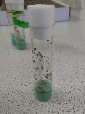
One reason for Drosophila’s success as an experimental model system is its straight forward maintenance in the laboratory environment. This enables scientists to breed large numbers of flies, and to generate and keep large numbers of genetically distinct stocks with relative ease and at comparatively low cost. Fruit flies are commonly reared in vials (glass, polystyrene or polypropylene) containing a small quantity of food (Figure ). Fly food is prepared in batches by cooking a mixture of water, glucose, yeast, agar and wheat flour in a kettle. Fungicides and antibiotics are added to prevent spoilage by microorganisms. Optionally dyes may be used to colour code batches. Food must be dispensed into vials whilst it is molten (above 50°C), as it solidifies at room temperature.
A vial of fruit flies. The food is at the bottom of the vial and the flies can be seen crawling over the inside wall. Green dye has been added to the food to identify the batch; normally the colour of fly food is pale yellow/brown. The vial has a height of 80 mm and a diameter of 25 mm.
In the fly facility of the Department of Zoology, University of Cambridge, vials used to be filled one at a time by a technician using a neoprene tube and a peristaltic pump. One end of the neoprene tube would be anchored in the kettle of food and the other inserted into the vial to be filled. The technician would activate the peristaltic pump () by pressing a foot switch until the desired volume of food had been dispensed into the vial. The free end of the tube would then be moved to the next vial to be filled and the process repeated. This work flow was laborious, messy, and consumed the valuable time of skilled technicians. Nevertheless, this continues to be standard practice in many fly facilities around the world.
There is an automated fly food dispenser on the market, but it is prohibitively expensive for many academic fruit fly facilities, including our own. We set out to design an open hardware solution to share with the scientific community.
Overall Implementation and Design
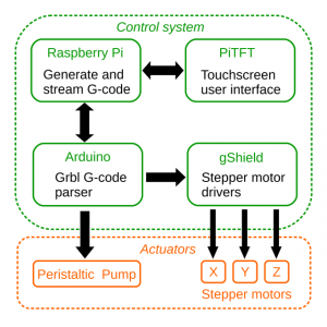
Vials are stored in cardboard boxes in a 10 × 10 grid. This ordered arrangement facilitates automated filling using a robot with three axes of motion (Figures and ). Coordinated movement of the x, y and z actuators places a dispensing nozzle over the mouth of a vial and a peristaltic pump is activated to deliver food. Top level control is provided by a Raspberry Pi with a touchscreen user interface. G-code () instructions are generated on the Raspberry Pi and then streamed to Grbl (; ), a G-code parser, running on an Arduino Uno (Revision 3). Grbl uses a gShield (; ) to translate the G-code instructions into digital pulses which drive the stepper motors of the X, Y and Z actuators. The selection and specification of components are described in more detail below.
System architecture.
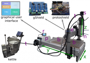
System overview. The cartesian coordinate robot has three axes of motion (x, y and z). A Raspberry Pi (r) generates and streams G-code instructions to an Arduino (not shown) which drives stepper motors (s) via the gShield. A protoshield is used for custom electronics; visible on this circuit board are the capacitors used to filter noise on the limit switch lines, and the two optocouplers which are the interface to the peristaltic pump (p). The gShield and protoshield are stacked on top of the Arduino and housed in the electronics box (e). A graphical user interface is displayed on the touch screen of the Raspberry Pi (r). Fly food prepared in the kettle is propelled through neoprene tubing (t) by the peristaltic pump (p) to the nozzle (n) from where it is dispensed. Boxes (b) of vials are loaded on to the platform of the robot for filling.
Rather than attempt to design our own cartesian coordinate robot, we decided to adapt an existing machine. We originally planned to use a cheap, mass-produced, desktop CNC (Computer Numerical Control) router. However, modifying a commercial CNC router would require some, potentially challenging, reverse engineering. Additionally, a commercial router would include components not required for this project, such as a spindle.
An open-hardware router provided a much more flexible starting point, because the design could be modified before commencing the build. Of the numerous open-hardware router designs available online, we chose Mark Carew’s “routy” () for the following reasons:
- All parts were readily available.
- The OpenBuilds community forum showed that other people had successfully built functioning routers using this design.
- This bed of this router is a suitable size to accommodate two boxes of vials.
- It was relatively cheap to build.
This cartesian coordinate robot uses belt and pulley actuators for the X and Y axes, and a leadscrew actuator for the Z axis. Grbl (; ), an open source G-code parser provides CNC motion control. Key features of Grbl include precise timing, asynchronous operation and acceleration management. Grbl is written in optimized C and runs on an Arduino. The Arduino cannot drive the stepper motors directly and so a gShield (; ) is required to provide the hardware interface (Figure ). Header pins on the gShield enable it to be mounted directly on top of an Arduino Uno.
We opted to use the combination of Grbl, Arduino Uno and gShield, because they had been shown to be an effective solution for CNC motion control in the original “routy” design. However, alternative open hardware CNC controllers are available, and could potentially be used in this build. For example, the functions of the Arduino Uno and gShield are combined in the SmoothieBoard () and the TinyG (; ). The SmoothieBoard and TinyG each have their own open source G-code parser.
For this project, some minor modifications to the “routy” design were required, including:
- A pair of limit switches were added to each axis to define the range of motion. The limit switches are also used for ‘homing’; i.e. setting the origin of the coordinate system.
- The z-actuator was lengthened to give greater range in the vertical axis, and thus enable to robot to handle vials of a variety of sizes.
- The gantry was raised to provide more clearance from the bed of the router.
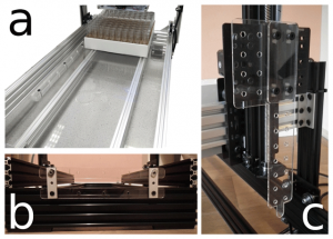
- A router would normally have a sacrificial bed. This has been replaced with an acrylic platform with guide rails to ensure the correct alignment of the boxes of vials in the x-axis (Figure ). The platform can be removed from the robot and disassembled for cleaning.
- A fence has been added to facilitate alignment of boxes in the y-axis (Figure ).
Parts laser cut from acrylic sheet. (a) Platform with guide rail to ensure correct alignment of boxes; can be disassembled for cleaning. (b) Fence to prevent boxes of vials from being pushed off the platform and to ensure their correct alignment in the y-axis. (c) Mount for the neoprene tube and nylon nozzle that deliver the fly food to the vials; cable ties are threaded through the holes to attach the tube and nozzle assembly.
The Cole-Parmer Masterflex peristaltic pump () is used to manually fill vials. We decided to incorporate one of these pumps into our build for the following reasons:
- Long term use in our fly facility has demonstrated the reliability of the pump.
- The pump can be operated by remote control (via cable), which is prerequisite for integration into a robotic system.
- We had one at our disposal.
A promising open hardware alternative to this commercial pump has been developed by iGEM (International Genetically Engineered Machine) 2017 team Aachen (; ).
To fill vials of fly food we simply need to be able to start and stop the pump. However, for other applications it may be necessary to control the direction of flow. The remote control interface on the peristaltic pump is a DB15 female port. Closing contact between pins 10 and 12 starts the pump; breaking contact stops the pump. The pump can be switched from clockwise (CW) rotation to counterclockwise (CCW) rotation by closing contact between pins 11 and 12. In the operation of a CNC router Grbl uses Arduino pins A3 and D13 for enabling coolant and changing spindle direction respectively. Here we use A3 for pump stop/start and D13 for pump direction (CW/CCW). Two optocouplers are used to connect the Arduino to the pump while maintaining electrical isolation. When Arduino pin A3 is high (i.e. set to 5 Volts), one of the optocouplers makes contact between pins 10 and 12 on the DB15 port starting the pump.
A neoprene tube with a nylon nozzle is used to deliver food to the vials. To attach this assembly on to the z-actuator of the robot we designed a mounting plate which was cut from a sheet of acrylic (Figure ). Cable ties are threaded through the holes to attach the hose assembly.
Several electronic components must be wired to the Arduino, including optocouplers for interfacing with the peristaltic pump, and capacitors for filtering noise on the wires from the limit switches. These components are mounted on an Arduino protoshield (Figure ). A protoshield was chosen over a custom printed circuit board, because (i) it can be conveniently stacked between the Arduino and gShield boards; and (ii) it is cheap and readily available to anyone wishing to replicate the robot. Circuit diagrams for the custom electronics are provided on .
Movement of the robot is programmed in G-code. A computer is required to generate G-code programs, and also to stream them to the Grbl software running on the Arduino. We chose a Raspberry Pi, on the basis of its small footprint, low energy consumption, and low cost.
A touchscreen attached to the Raspberry Pi presents a graphical user interface (GUI) to the operator of the robot (Figure ). A GUI was chosen over hardware switches, because it could be rapidly reconfigured to add or remove functionality as required. A resistive rather than a capacitive touchscreen was selected for this application, because some operators may wear gloves.
The system is inherently modular (Figure ), facilitating further customization. Should a module cease to be available, it will be possible to substitute an alternative. For example:
- A different router design could be chosen to provide linear actuators.
- The touchscreen could be replaced with mechanical switches.
- The Raspberry Pi could be substituted for a spare laptop or desktop computer.
- A SmoothieBoard () or TinyG (; ) could replace both the Arduino and gShield.
(2) Quality control
Safety
Operators of the robot should be aware of three hazards:
- Electric shock.
- Entanglement or entrapment in moving parts.
- Slips, trips and falls.
The power supply runs on mains electricity and so should be positioned well away from the robot where there is no danger of it being splashed with liquid. Additionally, use of a residual current device (RCD) is recommended to protect operators from electrocution. The actuators of the robot use low voltage (24V) motors. All cables should be inspected for damage before switching on the robot.
Precautions should be taken for loose hair, clothing, jewellery and other items so that they are not caught in the machine. Trays of vials should be loaded and unloaded when the actuators of all three axes are stationary. The touchscreen handset allows the operator to start and stop jobs while standing well clear of the moving parts.
Cables and neoprene tubing should be positioned so that they do not pose an obstruction or tripping hazard. Spillages of fly food to be cleaned up immediately to avoid slip hazard.
Calibration
Before the robot can be used, it is essential to calibrate the motion of the actuators, determine the cartesian coordinates of the vials to be filled, calibrate the flow rate of the peristaltic pump, and generate G-code programs for filling vials. These procedures are described in detail in the user manual (live: ; archive: ), and summarized below.
The step size (steps/mm) of the stepper motor(s) on each axis must be calculated, so that Grbl can calculate the number of digital pulses required to move an actuator a known distance (). Grbl can automatically find the origin of the cartesian coordinate system by running a homing cycle in which the actuators are driven in the positive direction until the limit switches are activated. The step size of the linear actuators is calculated on completion of the build, and this calibration procedure should not need to be repeated unless the motors or timing belt are replaced.
The platform of the robot can accommodate two boxes, each containing 100 vials (). The guide rail and fence ensure that the boxes are always placed in the same position (Figure ). The robot must be given the coordinates of every vial to be filled. If we know the xy coordinates of the vials in diagonally opposite corners of a box, we can calculate the coordinates of all other vials in the box by interpolation. We also need to determine the appropriate height (z coordinate) of the nozzle for filling vials; sufficient proximity to the mouth of the vial to ensure accuracy of food delivery, but not so close that it might strike the vial when moving laterally. A step by step protocol for determining vial coordinates is provided: . This procedure is performed once and would only need to be repeated if the size of the boxes or vials changed.
To maximize speed the peristaltic pump is run at its maximum flow rate of 30 ml/second. In our fly facility, we add 8 ml of food to each vial, therefore based on the maximum flow rate, we should only need to run the pump for 0.27 seconds to dispense 8 ml of food. However, there is latency in the system and the pump does not reach its maximum flow rate instantaneously on activation. Therefore, it is important to determine the fill time empirically. We do this by programming the robot to test fill a single box of vials using a range of fill times; one per row. The volume of food in the vials can then be measured and the optimum fill time identified. A script has been written for this purpose and more details can be found in the manual: .
Two G-code programs are required, one for filling a single box of vials, and another for filling two boxes of vials. We have written a python script to generate these G-code programs; it requires the following parameters:
- the fill time, as determined in the calibration of the flow rate of the peristaltic pump
- the appropriate height (z coordinate) of the nozzle for filling vials
- the time the robot should wait after filling a vial, to allow for drips of food from the nozzle, before moving on to the next vial (default value of 0.1 seconds).
Protocol and script for generating G-code programs: .
The precision and accuracy with which the robot aliquots fly food to vials was assessed by measuring the depth of food in each of 100 vials. The volume of food in each vial was estimated using the following formula:
where r is the internal radius of the vial and h is the depth of food. The estimated volume of food in each vial ranged from 7.1–8.3 ml (mean = 7.7 ml; standard deviation = 0.27 ml). For comparison, 100 manually filled vials contained an estimated 7.5–9.1 ml (mean = 8.3 ml; standard deviation = 0.25 ml) of food. The variation reported here is probably inflated by measurement error.
General testing
(3) Application
Use case
To date the robot has been applied solely to the use case of filling vials of fly food. A video showing the robot in action is available at: .
Reuse potential and adaptability
The system in its current form could be applied to other low precision liquid handling operations, such as dispensing reagents. The design includes the electronics required to control the direction of rotation of the peristaltic pump, so the system could be programmed (in G-code) to extract liquid from one vial and transfer it to another. More generally, a cartesian coordinate robot can be used to automate many tasks in the laboratory, such as moving a camera to capture macroscopic images of museum specimens arranged in trays () or positioning an extruder for 3D bioprinting ().
Support
The robot has yet to be replicated in other labs and so a community of users has still to be established. Nevertheless, support communities are associated with all of the constituent open hardware and software components:
- Arduino ()
- CNC router ()
- grbl ()
- gShield ()
- Raspberry Pi ()
- TkInter ()
(4) Build Details
Availability of materials and methods
All materials are readily available from online suppliers. A complete bill of materials, including URLs of vendors, is provided on . There are two specialized hardware components which are produced by only one manufacturer: the Cole-Parmer Masterflex peristaltic pump and the gShield CNC motion controller. The peristaltic pump is mass produced and so should be easy to acquire, but could be substituted with a device of similar specification. The gShield is one of several CNC motion controllers. Should production of the gShield cease, suitable alternatives include the SmoothieBoard () and TinyG (; ). Moreover, circuit diagrams for the gShield are available (; ) and so the device could be fabricated.
Access to a laser cutter will be required to cut the acrylic parts (tube mount, platform and fence rails). A mitre (chop) saw is needed to cut the V-Slots™ Aluminium extrusion.
Ease of build
The robot can be assembled using standard workshop tools (i.e. spanners, screw drivers, Allen (hex) keys and a soldering iron). Detailed documentation on the build process is available on , with every step illustrated with a photograph or diagram. Similarly, comprehensive instructions on software installation and configuration are provided on github: (archived in ).
Operating software and peripherals
- Adafruit’s custom raspberry pi image (), based on Raspbian version 8 (‘jessie’; kernel release 4.4.24-v7), is pre-configured for use with the PiTFT touch screen and contains all required software dependencies. Alternatively, Adafruit provide a helper script () to customize a standard Raspbian release for use with the touch screen.
- Grbl gcode parser (). Originally used version 0.9i and currently using version 1.1f () which was released on 01/08/2017.
- Arduino IDE () is required to load Grbl software onto the Arduino Uno.
- Python 2.7.9 scripts are used to generate all gcode programs used by the robot.
- The touchscreen user interface is developed using Python 2.7.9 and Tkinter (; Tk version 8.6).
Dependencies
- Raspberry Pi version 3 (). Earlier versions can potentially be used, but may require a different touch screen.
- Adafruit PiTFT Plus 320 × 240 2.8″ TFT + Resistive Touchscreen ().
- Arduino Uno, which is open source hardware under the Creative Commons Attribution Share-Alike license ().
- Arduino gShield (; ) provides the hardware implementation of the Grbl CNC motion control system.
- Cole-Parmer Masterflex Peristaltic Pump (). This commercial pump could potentially be substituted with an open hardware peristaltic pump.
- V-Slot™ Aluminium Extrusion by OpenBuilds is licensed under the Creative Commons – Attribution – Share Alike license ().
Name: CNC fly food dispenser
Persistent identifier:
Licence: CC-BY 3.0
Publisher: Matthew T. Wayland
Date published: 21/04/2017
Name: Cartesian coordinate robot for dispensing fruit fly food
Repository:
Persistent identifier:
Licence: GNU General Public License 3.0
Date published: 22/08/17
(5) Discussion
Conclusions
The cartesian coordinate robot described here is a cheap (at the time of writing, May 2018, the total cost of materials, excluding pump, was £650) and reliable tool for automating the production of vials of fly food. It does not provide greater speed, accuracy or precision than a human operator of a peristaltic pump. However, it does release skilled technicians from a tedious task that carries the risk of repetitive strain injury (). The entire system can be built and configured in one day. In our fly facility the robot currently saves our technicians around an hour of work each week.
This project is a testament to the power of open source hardware and software. Designing a cartesian coordinate robot from scratch would be a technically challenging task, beyond the skill set of the authors, who have no formal training in engineering. However, by building on existing open hardware (OpenBuilds “routy”, Arduino, gShield) and software (Grbl, Python, TkInter) projects, we have been able to develop an automated fly food dispenser with relative ease.
Future Work
The current system is fully functional and very reliable. Nevertheless, in future iterations of the design, the following points should be considered:
- We had a commercial peristaltic pump at our disposal, and so it made sense to use it in our build. However, substituting the commercial pump for an open hardware alternative (e.g. ), would make the system easier and cheaper to replicate in other labs.
- The current system has a single nozzle and so food is delivered to one vial at a time. Multiple nozzles would allow several vials to be filled simultaneously, potentially saving time.
- The limit switches are wired in the normally open configuration, the Grbl default. Changing to a normally closed configuration would make the limit switches fail safe (i.e. in the event of a fault in any of the limit switch circuits, it would not be possible to operate the robot).
- Further experimentation and testing is required to determine if the actuators can reliably be driven at higher speed and acceleration, and thus increase the rate at which vials are filled.
- Shields could be added to protect the actuators against food spatter, although this hasn’t been an issue in our facility.
- The cables connecting the cartesian coordinate robot to the power supply, raspberry pi and peristaltic pump are enclosed in spiral wrap, which provides some protection against entanglement with the actuators. However, a chain style cable carrier system would be a more reliable solution to this problem ().
Additional File
The additional file for this article can be found as follows:
Hardware design files. DOI:
Acknowledgements
We are indebted to the developers of the open-hardware and free software on which this project is based. We would like to thank Tracey Brazier and Oksana Elliott (Department of Zoology, University of Cambridge) for testing the robot and providing feedback on its performance. Dr José Casal (Department of Zoology, University of Cambridge) secured funding for the materials. This project would not have been possible without the Cambridge Makespace (). We would like to thank the reviewers, Mainardo Gaudenzi Asinelli, Tom Baden and an anonymous individual, for helpful feedback on our manuscript.
Funding Information
The project was supported by a Wellcome Trust Grant (WT096645MA) to Peter A. Lawrence.
Competing Interests
The authors have no competing interests to declare.
Author Contributions
ML conceived the idea of modifying a CNC router to dispense fruit fly food. MTW built and documented the robot. MTW wrote the first draft of the manuscript, which was improved by feedback from ML.
References
Adafruit 2018a Adafruit PiTFT 2.8″ touchscreen display for Raspberry Pi: Easy install. Perma Link: (visited on 06/16/2018).
Adafruit 2018b Adafruit PiTFT 2.8″ touchscreen display for Raspberry Pi: Overview. Perma Link: (visited on 06/16/2018).
Adafruit 2018c Raspberry Pi installer scripts: adafruit-pitft.sh. Perma Link: (visited on 06/16/2018).
Banovic, L and Vihar, B 2018 “Development of an Extruder for Open Source 3D Bioprinting”. In: Journal of Open Hardware, 2(1): 1. ISSN: 2514-1708. DOI:
Blagoderov, V, et al. 2012 “No specimen left behind: industrial scale digitization of natural history collections”. In: ZooKeys, 209: 133–146. ISSN: 1313-2989. DOI:
Carew, M 2018 ROUTY CNC Router (V-Slot Belt and Pinion). Perma Link: (visited on 06/16/2018).
Cole-Parmer 2018 Masterflex L/S: An accurate digital pump drive for critical metering and dispensing applications. Perma Link: (visited on 06/16/2018).
El-Helaly, M, Balkhy, HH and Vallenius, L 2017 “Carpal tunnel syndrome among laboratory technicians in relation to personal and ergonomic factors at work”. In: Journal of Occupational Health, 59(6): 513–520. DOI:
Fisher Scientific 2018 Drosophila products and supplies. Perma Link: (visited on 06/27/2018).
gnea 2018 Grbl: An open source, embedded, high performance g-code-parser and CNC milling controller written in optimized C that will run on a straight Arduino. URL: (visited on 06/17/2018).
Held, LI, Jr. 2017 Deep Homology? Uncanny Similarities of Humans and Flies Uncovered by Evo-Devo. Cambridge: Cambridge University Press. ISBN: 9781316601211.
Synthetos 2018a Affordable Industrial Grade Motion Control. URL: (visited on 06/17/2018).
Synthetos 2018b Arduino gShield: Archived source code and hardware design files. Perma Link: (visited on 06/17/2018).
Synthetos 2018c The Arduino gShield: A complete hardware solution the grbl CNC motion control software. URL: (visited on 06/17/2018).
Synthetos 2018d TinyG: Archived source code and hardware design files. Perma Link: (visited on 06/17/2018).
Wayland, M.T. and Landgraf, M., 2018. A Cartesian Coordinate Robot for Dispensing Fruit Fly Food. Journal of Open Hardware, 2(1), p.3. DOI:
Wayland MT, Landgraf M. A Cartesian Coordinate Robot for Dispensing Fruit Fly Food. Journal of Open Hardware. 2018;2(1):3. DOI:
Wayland, M. T., & Landgraf, M. (2018). A Cartesian Coordinate Robot for Dispensing Fruit Fly Food. Journal of Open Hardware, 2(1), 3. DOI:
Wayland MT and Landgraf M, ‘A Cartesian Coordinate Robot for Dispensing Fruit Fly Food’ (2018) 2 Journal of Open Hardware 3 DOI:
+ General Reviews