Build an Adorable Wobble Bot from Upcycled Cans Make:
|
|
Build an Adorable Wobble Bot from Upcycled Cans Make: Basic Data Category: Projects URL (first publication): https://makezine.com/projects/wobble-bot-upcycled-cans/
no no
Other
Design files are in original format: No Free redistribution is allowed licence: No
|
Description
Build an Adorable Wobble Bot from Upcycled Cans
- By
- Time Required: 3-8 Hours
- Difficulty: Moderate
Photography by Ben Light
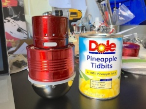
After preparing a tasty pineapple snack, you will have the raw materials to build your own wobbling robot toy. This little guy will shake and vibrate when you turn his head. There is a lot of machining and electronics work in this project, so feel free to tweak the robot recipe if you have better ideas or techniques.
Step 1: Eat Something and Gather Materials
First make some (use canned pineapple chunks), it’s easy to prepare and goes great with vanilla ice cream.
When you’re finished you’ll have the major building blocks to make the Wobble Bot: a spice container, a pineapple can, and half sphere form.
Remove the paper label and clean out the can. Remove the magnetic backing on the spice container, it peeled off easily for me.
Step 2: Modify Can
Find the center of the can, mark it, and drill a ⅜” diameter hole.
Use a smooth edge can opener to remove the incredibly sharp lip on the can.
Drill ⅜” hole for cables about 1″ from center.
Drill ⅛” diameter holes on each side of the can (two holes altogether), about ⅜” from the lip of the can. These holes will eventually attach the can to the coupling ring.
Step 3: Drill Holes in Half Sphere
Drill six evenly spaced ⅛” diameter holes about 0.185″ from the edge of the half sphere.
These holes will eventually attach the half sphere to the coupling ring.
Step 4: Assemble Weight
Attach one lamp nut to the threaded nipple. Stack all of the washers and lamp weight on the threaded nipple and attach the other nut.
Place the weight assembly inside of the half sphere.
Note: I had to modify the weight a bit on the metal lathe so it would fit properly inside the half sphere. If you don’t have access to a lathe, you can use .
Step 5: Create Coupling Ring
The point of the coupling ring is to attach the pineapple can to the half sphere. It could be made a few ways, (3D printed, a stack of laser cut rings…) but I turned one out of machinable plastic on the lathe.
One end must fit the inner diameter of the pineapple can (about 3.2″ diam), and the other end must fit inside of the half sphere (about 3.1″ diam).
There is also an inner lip of about .2″ that the circular perfboard sits on.
Overall ring dimensions (yours may vary): 3.45″ diameter, 1.25″ height.
Mark holes from the pineapple can and half sphere onto the coupling ring. Drill 3/32″ holes and tap 4-40 threads at all of the marks.
Mark two mounting holes for the perfboard and drill ⅛” holes.
Note: I didn’t love working with the machinable plastic. It was finicky and melted a bit. If I had to do it all over again I would probably make it out of Delrin.
Step 6: Motor Mount and Wobble Wheel
These plastic motor mounts are very convenient, but you will only need the round barrel part of the mount.
Sand or file a side flat, drill a 7/64″ hole, and tap 6-32 threads.
Screw the bracket to the plastic motor mount with a short 6-32 machine screw. Use washers if necessary. Solder jumper wires to the motor and place in mount.
Using a machine screw, a few washers, and a nut, place them between the wheel and o-ring (see photo). You will eventually have to fine tune the number and weight of washers used to get the best wobble motion.
Step 7: Place Motor Mount
Insert motor mount assembly inside of the pineapple can. The end of the DC motor should fit in the center hole. Mark and drill the hole to mount the bracket to the can. Use a short 6-32 machine screw, washer, and nut to secure the motor mount assembly.
Attach the wobble wheel to the shaft of the DC motor.
Step 8: Create and Assemble Potentiometer Stand
Remove the sliding bracket from the Adjustable Candelabra Socket.
Straighten the bracket and rebend it to fit around the potentiometer. Bend the ends so the screw holes will lie flat.
Mark and drill mounting holes in the pineapple can. Assemble using 4-40 machine screws and nuts.
Note: This could also be accomplished by drilling and bending a metal strip. There is nothing special about the bracket from the socket, I just had it laying around on my workbench.
Solder jumper wires to the on/off terminals and a 3 pin jumper to the potentiometer leads. I used a clipped off cable from a burned out servo motor. Tuck cables into the ⅜” hole.
Step 9: Assemble the Head
Mark and drill a ⅛” hole in the center of the spice container.
Drill a ⅛” hole in the center of the potentiometer knob. Place a machine screw inside the knob. Put the knob inside of the spice container, attach with washers and acorn nut.
Drill holes in the spice container for eyes — I drilled two ⅛” holes. After the container is powder-coated, hot glue a piece of vellum to the inside.
Step 10: Solder and Assemble Circuit
The circuit I used is heavily influenced by Dustyn Roberts’ book , pages 159-162.
Potentiometer
DC Toy Motor
555 Timer IC
Capacitor, 0.1uF (2)
Tip 120 Transistor
Voltage Regulator
9 Volt Battery and Connector
Component layout is important. All tall components should be placed along the perimeter of the perfboard or bent to lie flat. Also, there should be no connections made along the center strip (denoted by the blue tape). The 9V battery will eventually be placed underneath the perfboard and this will avoid any potential short circuits. I used male header pins to connect to the motor and the potentiometer.
Notch out one corner of the perfboard for the battery clip.
Make sure to disassemble all of the components first and properly clean all of the parts before you powder coat.
Mount the circuit into the coupling ring using two 4-40 machine screws and nuts. Make sure to tuck the battery connector underneath the circuit board.
Step 11: Powder Coat the Parts
You can paint the parts any color, or with any technique, you’d like. I chose to powder coat some of the metal parts using .
Everything I know about powder coating I learned from . Make sure to disassemble all of the components first and properly clean all of the parts before you powder coat.
Step 12: Put it All Together
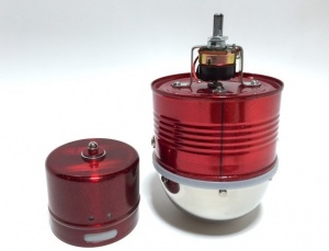
You should have four basic sections/assemblies of the bot at this point: the head, the body, the coupling ring, and the bottom half sphere.
Connect the motor and potentiometer cables from the body to the circuit board mounted in the coupling ring. Then screw them together using two 4-40 machine screws and washers.
Connect the 9V battery and double check that the motor is moving and everything is operational at this point.
Tuck the 9V battery under the coupling ring and turn it upside down. Place the weight assembly over the battery and then cover it with the half sphere. Screw in the six 4-40 machine screws.
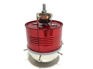
Slide the head onto the post of the potentiometer.
Congratulations, everything is assembled. Your Wobble Bot is finished
Going further
I eventually added some LEDs inside the head and body. But the effect was a little underwhelming. So I will be working on getting brighter lighting.
I think the wobbling needs a little fine tuning too. Maybe a little less weight at the bottom and a little more weight on the wobble wheel connected to the DC motor. But when the motor is set to the highest setting, I really like the spastic movements and the “evil” sounds it makes.
Happy bot building.
Parts
- Can of Pineapple, 8 oz. 3.35” diameter 2” tall
- DC Toy Motor
- Assorted machine screws, washers, and nuts, 4-40 and 6-32 threads
- Washers, 1-⅛” diameter (8)
- Plastic Vellum
- Circular Perfboard, 2-⅜” diam
- 555 Timer IC
- Capacitor, 0.1uF (2)
- Tip 120 Transistor
- Voltage Regulator
- 9V Battery Connector
- 9V Battery
- Male Headers
Tools
- Hand Drill and Drill Bits
- Center Finder
- Smooth Edge Can Opener
- Metal Lathe
- Tap 4-40 and 6-32
- Powder Coating Gun
- Glue Gun
- Screw drivers
- Wrenches
- Pliers
- Soldering Iron/Solder
Advertisement
Advertisement
Advertisement
Ben Light is a New York based maker, designer, and Cash Cab contestant. Ben's work has appeared in the Museum of Arts and Design, the MoMA Design Store, and on the shelves at Crate & Barrel. He earned a B.S. in Mechanical Engineering from Lehigh University and a Masters from NYU's Interactive Telecommunications Program (ITP).
Ben may love his lathe, just a little too much.
Advertisement
+ General Reviews