DIWire Bender Make:
|
|
DIWire Bender Make: Basic Data Category: Projects URL (first publication): https://makezine.com/projects/diwire-bender/
no no
Other
Design files are in original format: No Free redistribution is allowed licence: No
|
Inhaltsverzeichnis
Description
DIWire Bender
Build an automated wire bender.
- By
- Time Required: Probably a day or two
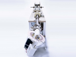
D.I.Wire Bender is a rapid prototype machine that bends metal wire to produce 2D and 3D shapes, pushing the limits of what can be produced in different materials, forms, and methods, anywhere from a model shop to your home.
For the code, full bill of materials (parts list), and readme files, visit the project page on our
The files can be found under Download. The code can be found under Source/Browse.
Tools
Advertisement
Advertisement
Advertisement
Steps
Advertisement
- Follow wiring diagram to connect the electronics. See the program and wiring diagram to get the pinout for the Arduino.
- Connect motors to the drivers - this wiring depends on the motors and drivers you select. If you use the ones we did, its a quick connect with a Molex connector.
- Connect drivers to the Arduino. Most motor drivers have a direction, pulse and common ground wires or CW pulse, CCW pulse and ground. These are the ones you are mostly concerned about. Some have "all windings off" and other options.
- Connect one of the solenoid of the leads to the power supply.
- Connect the relay DC control to the Arduino pin and the common ground. If it's a solid state relay, be sure to connect it in the right direction, or it won't switch. Connect the Normally Open (NO) lead to the power supply and the other side to the solenoid.
- Put the steel gear on the bender motor, and the knurled knob on the feeder motor. Don't put the nylon gear on the Z-bend motor yet.
- Before the next step, test the Arduino and Processing programs to make sure the gears turn and the solenoid moves as expected.
- Drill all the holes in the top base. Reference the STEP file in the Google Code download files.
- These dimensions are not very critical, but there are a couple of things to keep in mind if you want to do it without referencing the file:
- The straightner wheels should just touch.
- The center line of the wire should follow a straight path from the straightener to the guide, to the tangent of the knurled knob, to the tube.
- Attach plastic mold to top base.
- Put in Z-Motor. (Make sure to keep the screws loose until the end to make it easier when attaching the gear.)
- Attach nylon gear to Z-Motor.
- Attach feeder motor to top base.
- Tighten everything down.
Install support beams and triangles.
- Attach Velcro to base to attach the Arduino, motor drivers, breadboard terminal and power supply.
- Attach top base to bottom base. We used 80/20 10mm profiles, but anything would do — a piece of ply would be good. The height is not critical, just enough to clear the motors.
Attach switch to battery and top board.
- Slide the pillow blocks onto the tube.
- On one end of the tube attach the other nylon gear. This will interface with the Z-motor. Note: Our gears did not come with hubs, so we made our own, but it's a lot easier to use a gear with a hub if you can find one.
- Loosely attach the metal shaft mounts to the other end of the tube.
- Attach the tube assembly to the top plate. We used a couple of washers to space the gears apart so they turn smoothly.
- Remove 90 degrees from the last nylon gear so it fits onto the solenoid base.
- Attach gear to base.
- Put solenoid into base.
- Slide the brass bushing into the base. This allows the solenoid pin to slide smoothly, and spreads the load so the base doesn't crack.
- Attach the solenoid assembly with the shoulder bolt.
- Put the spring into solenoid hole.
- Drop solenoid pin into hole.
- Drop the extension pin into hole and stick a cross-pin through the hole to keep it together.
- Construct feed lever arm. We used an aluminum 1" x 3/4" x 1/8" thick U-channel. The wheel is 3/4" brass bar — a grooved roller bearing works well too. The length and location of the holes is not critical, as long as the wheel presses on the wire at the location of the knurled knob.
- Attach the lever arm to the top base.
- Attach an angle bracket with a bolt so the bolt applies pressure to the end of the lever arm.
- Construct straightening wheels.
- Attach wheels to top board. You can use a staggered pattern instead of the linear pattern in the photos. You can also have straightener wheels on multiple planes so you straighten the wire from multiple directions.
- Attach the wire feeder at the end of the top board.
- Attach spool to wire feeder at the end of the board.
- Voil You're done Tell us how it turns out — — and we'll post it on . Enjoy
Conclusion
You need a shop to do this project. Have fun
Advertisement
+ General Reviews