Development of an Extruder for Open Source 3D Bioprinting
|
|
Development of an Extruder for Open Source 3D Bioprinting Basic Data Category: Projects URL (first publication): https://openhardware.metajnl.com/articles/10.5334/joh.6/
no no
Other
Design files are in original format: No Free redistribution is allowed licence: No
|
Inhaltsverzeichnis
Description
Development of an Extruder for Open Source 3D Bioprinting
Abstract
Bioprinting has gained significant traction in recent years due to it’s implications for medicine and research with a growing spectrum of potential applications. The focus of this work lies on developing an open-source piston driven syringe extruder with thermo-regulation, that is compatible with various CNC systems but also provides broad control and functionality. The manuscript describes the construction and evaluation of the extruder, as well as extrusion parameters and tested fabrication capabilities.(1) Metadata Overview
- Replication(a): This project has been independently replicated by non-author members of our institute ()
- See section “Build Details” for more detail.
Introduction
Bioprinting is a rapidly developing field of research, gaining a lot of attention in recent years, connecting science, medicine, as well as engineering (). In general, it is a method of digital fabrication, similar to various commonly known types of 3D printing with polymers, with the difference that it is used with biological and biocompatible materials, which act as a 3-dimensional substrate for cells (, ). Cells can be printed simultaneously with the matrix material, or applied to the finished scaffolds afterwards (). There are many possible applications, ranging from in vitro tissue modelling and testing, to tissue fabrication and organ growth (, ) as well as microfluidics, lab-on-a-chip devices, dental fillings, etc. (, , ).
While it is already deployed in practice (, , ), the current state of the technology still has many limitations. The price of commercial solutions, either the devices themselves or the custom made cartridges/bioinks, is still very high (). Also, the fabrication itself is yet to reach the requirements of organ manufacturing: resolution, compatibility with multiple cell types, biodegradability, stability, sufficient medium perfusion of the fabricated structures, etc. ().
Classical 3D printing, such as polymer filament deposition or lithographic prints, has become very inexpensive and widely available, since the technology was made open source. This has accelerated new innovations and stimulated fast technology development (). We second the view expressed in the literature, assuming that something similar should happen with 3D bioprinting when it becomes more accessible ().
3D bioprinters can be classified as CNC machines and belong to the same group with laser cutters, 3D printers or CNC mills and routers. The operating tool, which is the differentiating part between the listed machines, is attached to the head of the CNC machine which is operated using a computer software. The translational movement of the head of such machines is fully defined and controlled via 3 axes (x, y and z). In the case of bio-printer the tool attached to the head is an extruder where bio-material(s) are extruded. See Figure ) for better understanding.
a) Shows a small CNC machine with the integrated Vitaprint extruder, as used during this project; b) S3D CAD model of Vitaprint extruder designed in SolidWorks 2015.
The goal of this project was to develop “Vitaprint” – a device suitable for, but not exclusive to, bioprinting. Thus the motivation was to provide an open source, self-contained extruder, which should:
- be low cost and made from widely available materials
- allow aseptic mounting and deposition of materials
- allow for the use of highly viscous materials
- support thermo-regulation
- operate at a resolution comparable to current commercial systems
- be transferable to a broad spectrum of CNC systems
Overall implementation and design
the hardware of Vitaprint is divided into two parts, namely the CNC part and the extruder. The CNC construction of a miniCNC design was used, which is a small and robust version of a standard 3-axis CNC router. The support was made of steel and holds in place the aluminium head and table. Stainless steel rods were used with ball bearings to ensure smooth movement. Linear motion is controlled by three Nema32 stepper motors coupled with ball screws. The second part of the Vitaprint hardware is the syringe extruder. The extruder was entirely built out of aluminium. Most of the parts were milled out of 5 mm aluminium plate to keep the manufacturing easy. Two parts were manufactured out of thicker aluminium and require more advanced CNC milling skills.
The extruder was designed for use with standard plastic syringes, which provide many benefits: they are widely available, cheap and come in sterile packaging. Also, they are compatible with a wide range of different needles, which can be used as nozzles. To minimise the need to customise the syringes, a motorised drive system was designed, which is often used for DIY syringe pumps (, ). Other advantages of a motorised piston drive include the fact that it does not require an external pumping system, and the improved extrusion control, especially for viscous materials (), in comparison to pneumatic systems. The aluminium construction provides structural support to the cartridge and has good heat conduction, allowing thermo-regulation, which significantly increases the added value of the extruder. Many syringe-pump-derived extruder designs are already available on-line, but they are almost universally made from plastic, limiting their usability with materials that exploit thermal gelation. For thermal control the syringe housing contains integrated spaces for a thermistor and ceramic heaters. The regulation can be operated externally using commercial temperature controllers or open-source solutions. As an example, one arduino based open source heat regulator developed by us can be found under build details.
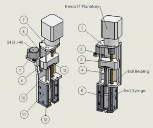
The presented extruder version contains two motors, a powerful stepper motor with a planetary reductor for extrusion (which requires low speeds but high torque) and a small bipolar motor for moving the extruder in the z direction. The overall design is described in more detail in the build chapter below, where a schematic of the extruder is also shown in Figure .
Universality of the design
The complete extruder was designed to be a self-contained unit, meaning that it works as a standalone syringe pump, given suitable motor control software. As a result, the user can choose which CNC system to attach it to. Moreover, multiple extruders could be used simultaneously. Most high-end 3D bioprinters offer multiple-extruder technology and allow fast extruder switching (). Using disposable plastic syringes as material cartridges is, as discussed above, beneficial due to their wide availability, sterile packaging and low cost. While their plastic composition makes them sensitive to higher temperatures and pressures, structural stability is compensated to some degree by the aluminium housing into which the syringes fit tightly. The direct motorised piston drive allows for the extrusion of materials in a wide range of viscosities and keeps the unit relatively compact.
Installation
This paragraph briefly describes the installation and usage protocol, after manufacturing and assembly of the extruder unit(s) are complete. For this project a Mini CNC mill by Planet CNC was used. The extruder was rigidly attached to the ‘head’ of the CNC mill (the platform which allows movement in all x, y, z directions) using M8 screws. For actual printing, a 5 ml syringe is installed into the extruder and the rest is operated via software. The exact procedure depends on the used CNC system, but typically includes the following steps:
(2) Quality control
Safety
Same as for other open source hardware, safety issues are partly subordinate to experience and skill of the user. Generally, there is no additional risk noted alongside standard safety considerations of CNC machines (CNC mills, 3D printers etc.). For work with cells, standard laboratory conditions and precautions should be considered. Working with animal cell lines typically requires at least safety level 1 laboratory standards established by the World Health Organization ().
Testing and measurements: Extrusion flow characterisation in 3D bioprinting using standard-size syringe and needle
One of the defining features of an extruder is its control and precision of extrusion, or in other words, the resemblance between actual extrusion, compared to the theoretical one. Resolution for example is determined by the nozzle and material behaviour. What we were especially interested in was the comparison of the piston movement to material flow coming from the tip. As our cartridges are made of relatively soft plastic (polypropylene) and usually have a rubbery piston cap, deformations may occur. This could substantially impact the extrusion, especially with the use of viscous liquids.
To test this, the extrusion was measured with an analytical scale (Mettler Toledo AT261) over time. For this purpose a liquid with high viscosity was prepared (50% gluten, 30% citric acid in water, end density: p = 1.16 g/ml) and was inserted into a 5 ml syringe with a G21 blunt-end needle. The syringe was attached to the extruder and the whole set-up was placed over a beaker to quantify the extruded material with a scale. To prevent non-linear evaporation effects, the beaker was filled with water and evaporation took place at a constant rate at the only air-water interface. This resulted in a linear drift in mass which was later on subtracted from the measurements. To minimise the evaporation drift and simplify the experimental set-up, water could be exchanged for less volatile liquids (e.g. sunflower oil), as shown in Figure . The extruded gluten mass change could then be isolated from the recorded data.
A block diagram of the extrusion experiment.
The mass change was logged with a frequency of approximately 3 Hz and plotted against the time progression. The predetermined piston movement (g-code) defines the amount of material that should ultimately be extruded, and was used to calculate the theoretical maximum extruded mass (mmax). While the measured mass was expected to reach this value, the curve progression would depend on possible elastic components in the extruder. A schematic of the experiment is shown in Figure .
In the first iteration of the constructed extruder, a Nema14 non-captive linear stepper motor was used. The displacement of the motor theoretically follows a linear time progression assuming the force exerted on the shaft is low enough for stepper motor to not skip steps.
A series of volumes (V = 2, 4, 6, 8 and 18 mm3) were extruded from the syringe. For every measured volume, a series of 4 measurements per feed rate (1 mm/s, 10 mm/s and 100 mm/s) were performed and the mass was recorded for 2–5 minutes. The measured drift line (evaporation) was subtracted from every measurement and mass-time curves were plotted. The rubber cap covering the piston was expected to be the major contributing factor to the elastic behaviour. Thus, in addition to measuring extrusion with regular syringes, the experiments were also replicated with o-ring syringes for comparison. The o-ring rubber seal of the plunger should significantly reduce elasticity (). A comparison of the seal structures is shown in Figure .
Regular rubber plunger cap (left) and o-ring cap (right).
Our assumption was that the mass extrusion had an elastic response and would follow the progression demonstrated in Figure .
Expected plunger displacement (orange) and extrusion mass flow (blue) behaviour. The target mass and the latency are also shown.
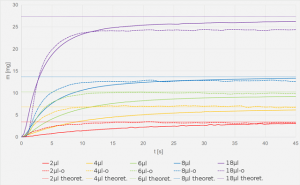
Results of the extrusion measurements at the sample feed rate of 100 mm/min are shown in Figure .
Comparison of gluten extrusion curves. Extruded mass was measured (vertical axis) and plotted against time (horizontal axis). The averaged mass curves of the syringes with the rubber seal are shown in blue, o-ring syringes in red and mmax values in yellow. Only F100 (feedrate = 100 mm/min) results are shown here, as the varying feed rates show no significant effect in such small steps.
In both cases the extrusion curves begin with a steep linear progression, but soon enter an asymptotic approach towards the target mass mmax. The curves of both tested syringes resemble stress-strain curves of polymers in their shape (). The o-ring curves reached saturation sooner, which was evident especially for smaller extrusion amounts. The feed rate on its own did not show any significant impact on the curve progression, as the graphs of 1, 10 and 100 mm/min all had a good overlap. While this may be surprising, it can be attributed to the viscosity of the gluten and its elastic behaviour, which is likely to compensate for the small amounts of extruded material. By reducing elasticity and increasing the amount of extrusion, the feed rate is expected to play a more important role.
A detailed analysis of the measured curves was performed by fitting an exponential fit to the mass-rate data. A script was written in Python 3 (the code is availabe on Github, DOI: ) to find the time point where mass reached 95% of the target mass and thus measure the latency (time delay to reach 95% mark) for every curve. The simple algorithm takes the raw data and fits the following exponential form:
Next, the time point is located where the fit line value reaches 95% of the maximum value of the fit in the given time range.
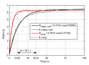
This was done for every set of data and afterwards, the latencies of the rubber cap and o-ring curves were compared. Not only were the latencies shorter for the o-ring plungers, they were also shorter with larger extrusion amounts (steeper beginning with a faster reach of the 95% mark). Thus, for 2 μl the time delay was approximately 57s, for 4 μl it was 25s, for 6 μl it was 12s and for 8 μl it was 7s respectively. A sample comparison between a rubber cap and o-ring syringe with 4 μl extrusion is shown in Figure .
Graph showing the difference in latency of the system with o-ring and rubber cap syringes. The reference point was chosen to be where extruded mass reaches 95% of the target mass.
It should be noted that while the o-ring syringe had significantly faster response times it also showed larger inconsistencies in the extruded material volume on average deviating from mmax more in comparison to rubber seal cap syringes which becomes apparent in Figure . There we can see that the o-ring syringe reaches 95% of the mass after 10.83s where the rubber seal syringe reaches 95% of the target mass only after 35.91s. Thin red and black lines represent the raw data recorded for o-ring and rubber syringes, respectively. Thicker lines represent the exponential fit to the recorded data. It is clearly visible on the graph in Figure that the fluctuation of the recorded data around the exponential fit is higher in the case of o-ring syringe compared to the rubber seal case.
The increased noise may be due to small bubbles contained in the gluten solution, the curve deviating from mmax, however, is likely due to the motor skipping steps at higher tensions. Therefore, the Nema14 was later replaced by a planetary Nema17 which allows for higher torque and smaller step sizes. The results confirmed the prediction. The density of the prepared mixture of gluten and citric acid was measured. Measuring the diameter of the syringe plunger and knowing the distance for which the plunger is moved during the experiment, a theoretical mass could directly be calculated. Then, the mass extruded during all cycles of a measurement was compared to the theoretical one. The average extruded mass was taken and the result was that in both cases the extruded mass exceeded the theoretical mass. The theoretical extruded mass at each extrusion step (0.1 mm plunger movement) was 0.014 g. In the case of the rubber cap the average extruded mass was 0.0158 g, values ranged between 0.015 g and 0.018 g, where in the case of the o-ring, the average extruded mass was 0.0152 g, values ranged between 0.0129 g and 0.016 g. This indicates an uneven extrusion which originates from the mechanics being non-concentric. By inspection, especially the link between the stepper motor shaft and threaded rod via coupler is a source of non-centric rotation of the threaded rod which causes irregularities in the vertical plunger movement. This, however, did not yet prove to be causing inaccuracies in practice, during bio-printing. The inconsistency of the extrusion could not be visually detected at any of the gluten samples.
As expected, the data suggested that a large portion of the system’s elasticity can be attributed to the seal cap. The elastic effect is especially apparent with slow extrusion. On the other hand, the o-ring syringes also exhibited elastic behaviour.
There are several potential sources of deformation which could cause elastic behavior of extrusion in addition to the rubber cap. For example the extruded material can contain small air bubbles, which could make the material locally more compressible and also cause inconsistent printing, see Figure . While this is material dependent, there are methods of reducing the amount of air inside the material, for example by vacuum exposure, centrifugation, sonification, etc. Ultimately, the syringes themselves can contribute to elasticity as well. Besides their benefits in other regards, being made out of relatively soft plastic (Polypropylene), allows bending when exposed to external forces, especially of the piston. While a full extrusion control cannot be provided at the current state, the current extruder is still suitable for general use with steady flow applications, even with very viscous liquids. To test this, scaffold building tests were performed.
Microbubbles captured in gluten scaffold using a microscope with 10x magnification. Air inside the filament adds a degree of elasticity to the system which causes difficulties in extrusion control and inconsistencies and tears in the filament.
Building scaffolds
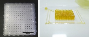
The extruder was installed onto a CNC mill system which was controlled with the Planet CNC software (URL: ). Two different materials were used with temperature dependent polymerization. Gluten (55% without Citric acid), which is a very viscous liquid and was printed at 50°C and a blend of 10% Gelatin and 1% Sodium Alginate (both components are already used for scaffolds in 3D bioprinting (, )), which was printed at 30°C. Two needle types were used, both blunt end: G21 with an inner diameter of 400 μm and G27 with an inner diameter of 200 μm. For the block formed scaffolds, g-code was designed by hand, ensuring round edges and a distance of roughly one needle width between parallel lines, depending on the needle, that was used. Two samples of the results are shown in Figure .
Testing the Vitaprint extruder using 10% w.t. gelatin and 1% w.t. alginate hydrogel (left) and 50% gluten (right). Nozzle diameter was 0.2 mm in for the gelatin and 0.4 mm for gluten due to higher material viscosity. Layer height is approximately double the nozzle height to avoid damaging the lower layer when the subsequent one is being printed.
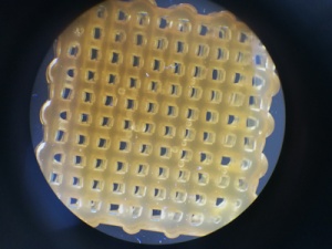
For gluten, only extrusion through the wider 0.4 mm needle was possible due to its high viscosity and relatively fast solidification when cooling from 50°C to room temperature. With the gelatin/alginate blend, printing with the finer needle was also possible and produced satisfying results. In terms of construction, the outcome is comparable to that of current state-of-the-art structures, as found in the papers by Zhengjie et al. (2016) or Malda et al. (2013) (, ). For a quantitative overview, basic analysis of the scaffold geometry was performed. Namely, the real size and theoretical size were compared and the size of the gaps in vertical and horizontal direction was statistically analysed. Histograms of the gap size distribution seen in the Figure were generated using Image-J 1.51a open source software.
Scaffold gap size variation. The sample from Figure was evaluated for printing precision. It’s outer dimensions were measured using a caliper to obtain a reference dimension. Using image processing, the size of 60 gaps in the vertical and lateral direction was compared to the outer dimensions of the scaffold. Histograms of horizontal (left) and vertical (right) gap sizes are presented above. The grey-scale legend shows the spectrum from smallest, to largest gap size in mm.
(3) Application
Use case(s)
Here we describe an example of operation, for the fabrication of a gelatine/alginate scaffold in the shape of a human nose. A finished sample is shown in Figure .
A 3D model of a human nose (left) and sample scaffold (right). The model was downloaded from the Thingiverse database and fabricated using a blend of 10% gelatin and 1% sodium alginate in water.
Reuse potential and adaptability
The syringe extrusion technology is easily used with other sol or gel materials (such as ceramic paste, other hydrogels etc.). The goal is to enable the user to 3D print almost any material that is in a liquid state, even with higher viscosity. Without a CNC system, the extruder can be used as a syringe pump with integrated thermo-regulation. Being open source, the design can be changed for other uses as well by modifying the design files found in the online repository (see below).
(4) Build Details
Availability of materials and methods
A schematic of the extruder is shown in Figure . Stepper motors 24BYJ-48 and Nema17 Planetary are required in addition to other the main parts, which are found in Table . Detailed build details with a full bill of materials and assembly instructions can be found in the documentation repository.
Numbered parts for assembly are described in the Table .
Table 1
Table of materials and tools for manufacturing and assembly.
| Part N. | Part Name | Material | Tool | Skill Level |
|---|---|---|---|---|
| 1 | coupler | aluminium rod φ 18 mm | lathe | basic |
| 2 | threaded rod | brass M5 | lathe | basic |
| 3 | nut | ABS plastic | 3D printer | basic |
| 4 | linear rod bearing | aluminium rod φ 3 mm | lathe | basic |
| 5 | syringe mount | aluminium block thick. 22 mm | CNC mill | advanced |
| 6 | threaded rod | brass M5 | lathe | basic |
| 7 | extrusion motor mount plate | |||
| 8 | backplate | |||
| 9 | switch motor plate | |||
| 10 | syringe top plate | 5052 aluminium plate 5 mm | CNC router | advanced |
| 11 | syringe mount side plate | |||
| 12 | syringe bottom plate | |||
| 13 | Finger Flange Plate |
Operating software and peripherals
For our testing and operation we employed a commercial, licenced copy of PlanetCNC software via USB (). In general, any CNC control software should be sufficient, as long as at least four axes can be controlled simultaneously. Devices which already have internal CNC operating software, such as many 3D printers, only g-code would be required, which can be generated from stl files using freeware, such as Cura or Slic3r.
Persistent identifier: e.g. DOI, etc.
Licence: CERN OHL v.1.2. license
Publisher: IRNAS
Date published: 13/04/17
Modifiable design files:
(5) Discussion
Conclusions
A syringe extruder was built with the goal of providing an open source solution for 3D printing of viscous liquids, hydrogels and pastes. To achieve this, the extruder needed to be: capable of working under high loads and providing precise extrusion control, while using low cost and widely available components.
Extrusion measurements have shown that real extrusion currently does not follow the stepper movement in a linear fashion, but rather with a delay and in the form of a stress-strain curve. This has been attributed to the elastic deformation of syringes and skipped motor steps under load. As a result, fast start-stop extrusion procedures are currently limited to materials with low viscosity. A quantitative analysis with a series of materials will be performed in the future in order, to determine the current viscosity limit. On the other hand, continuous flow applications, such as woodpile structures, are possible even with materials that have high viscosity, such as 55% gluten.
While elastic effects could be reduced by changing the rubber-cap on the piston to an o-ring, elasticity remains to some degree, manifesting as an extrusion latency. Three approaches can be employed to solve this problem:
- Structural improvement of the extruder, giving more structural support to the syringe and possibly the piston. It is unclear whether and to what extent the extruder itself can still be improved, while keeping the soft plastic syringes.
- Algorithmic linearisation by post processing the g-code to print with an inverted progression of a normal extrusion curve. If possible to implement, this could be the most effective solution, as it would also be useful for other extruder designs. It would, however, need to be adjusted for every material individually, by measuring its extrusion under typical usage conditions, calculating the inverse curve and post processing the g-code.
- Alternatively, flow rate regulation may also be implemented. Flow sensors are often used in pumping systems with sufficiently long and adaptable tubing. Our device, on the other hand, is designed to have the shortest possible way from syringe to target surface and to only contain sterile elements. Thus, regulation would only be possible by measuring the flow externally, e.g. by ultrasound, optical coherence tomography, etc.
If extrusion control can be optimised by the mentioned means, a stepper motor powered extrusion control seems not only a practical mechanism, as it does not require external piping/pumping systems, but also a low-cost solution. In addition, the disposable syringes and the accompanied needles can be a good solution for printing hydrogels. They are inexpensive, universally available and come in sterile packaging, thereby making aseptic printing significantly easier.
To conclude, while the design can still be improved, the developed extruder is well-suited for 3D fabrication of viscous solutions or gels aseptically under appropriate conditions (e.g. under a laminar flow hood). Being a self-contained unit it can be integrated into different CNC systems which may stimulate the increased use of this technology and accelerate its development.
Future work
Future work will primarily be oriented towards the points already mentioned in the conclusions section above: improving the design and compensating elasticity, to advance towards full extrusion control, allowing the fabrication of more complex structures.
In addition, printing new materials, some containing actual living cells will be tested, evaluating the cell survival of the printing process. This is an important stepping stone in tissue engineering and regenerative medicine. Depending on the required density and distribution of cells in the scaffold, both direct cell printing and post print application have their advantages in tissue engineering. Also, further improvements can be made to the device, by introducing new features, based on the experiences made with ours, but also other extrusion based devices, such as auto-levelling, multiple extruder technology and control, wireless control (reducing cabling around the device when in a laminar flow hood), etc.
Notes
1The data shown in this work was recorded using water.
2LINK: .
3.
Acknowledgements
Special thanks go to Mihael Miško who contributed with his experience and CNC operation and CAD skills towards faster develeopment of the extruder.
Funding Information
This project is financially supported by Shuttleworth Foundation through the fellowship of Luka Mustafa.
Competing Interests
The authors declare that all intelectual property is vested into Institute IRNAS and may be used for various purposes, not excluding commercial use.
Author contributions
Luka Banović has contributed towards the constructional design, assembly, documentation and paper writing.
Boštjan Vihar has contributed towards measurements and testing, literature review and paper writing.
References
Atala, A and Murphy, SV (2014). 3D bioprinting of tissues and organs. Nature Biotechnology 32: 773–785, DOI:
Dababneh, AB and Ozbolat, IT (2014). Bioprinting Technology: A Current State-of-the-Art Review. J. Manuf. Sci. Eng 136: 6–17, DOI:
Chua, CK and Yeong, WY (2015). Bioprinting: Principles and Applications. World Scientific, : 256–265. 978-981-4612-10-4
Guillemot, F, Mironov, V and Nakamura, M (2010). Bioprinting is coming of age: report from the International Conference on Bioprinting and Biofabrication in Bordeaux (3B’09). Biofabrication 2(1): 010201.DOI:
Hsieh, F and Hsu, S (2015). 3D bioprinting: A new insight into the therapeutic strategy of neural tissue regeneration. Organogenesis 11: 153–158, DOI:
Curodeau, A, Sachs, E and Caldarise, S (2000). Design and fabrication of cast orthopedic implants with freeform surface textures from 3-D printed ceramic shell. J Biomed Mater Res A 52(5): 525–535, DOI:
Habibovic, P, Gbureckc, U, Doillond, CJ, Bassetta, DC, van Blitterswijkb, CA and Barraleta, JE (2008). Osteoconduction and osteoinduction of low-temperature 3D printed bioceramic implants. Biomaterials 29: 944–953, DOI:
Mannoor, MS, Jiang, Z, James, T, Kong, YL, Malatesta, KA, Soboyejo, WO, Verma, N, Gracias, DH and McAlpine, MC (2013). 3D Printed Bionic Ears. Nano Lett 13(6): 2634–2639, DOI:
Sher, D (2015). The Top 15 Bioprinters, Available at: (Accessed on 22. Nov 2016).
Ozbolat, I and Yu, Y (2013). Bioprinting towards Organ Fabrication: Challenges and Future Trends. IEEE Trans Biomed Eng 60(3): 691–9, DOI:
Jones, R, Haufe, P, Sells, E, Iravani, P, Olliver, V, Palmer, C and Bowyer, A (2011). RepRap – the replicating rapid prototyper. Robotica 29(01): 177–191, DOI:
O’Murchu, LF (2014). How 3-D printing will radically change the world, CNBC. Available at: (Accessed on 30. Nov 2016).
Damase, T, Stephens, D, Spencer, A and Allen, P (2015). Open source and DIY hardware for DNA nanotechnology labs. Journal of Biological Methods 2(3): 24.DOI:
Frank, P, Haefner, S, Elstner, M and Richter, A (2016). Fully-Programmable, Low-Cost, “Do-It-Yourself” Pressure Source for General Purpose Use in the Microfluidic Laboratory. Inventions 1(2): 13.DOI:
Gere, JM (2004). Tension, Compression, and Shear in Mechanics of Materials In: 6th ed Toronto: Thomson Learning Inc., pp. 1–49. ISBN-10: 0534417930.
Lee, H and Cho, DW (2016). One-step fabrication of an organ-on-a-chip with spatial heterogeneity using a 3D bioprinting technology. Lab Chip 16(14): 2618–25, DOI:
Morgan, AJL, Hidalgo San Jose, L, Jamieson, WD, Wymant, JM, Song, B, Stephens, P, Barrow, DA and Castell, OK (2016). Simple and Versatile 3D Printed Microfluidics Using Fused Filament Fabrication. PLOS ONE 11(4): e0152023.DOI:
Obregon, F, Vaquette, C, Ivanovski, S, Hutmacher, DW and Bertassoni, LE (2015). Three-Dimensional Bioprinting for Regenerative Dentistry and Craniofacial Tissue Engineering. Journal of Dental Research, DOI:
Zhengjie, Wu; Xin, Su; Yuanyuan, Xu; Kong, B; Sun, W; Mi, S . (2016). Bioprinting three-dimensional cell-laden tissue constructs with controllable degradation. Scientific Reports 6DOI: Article number: 24474.
Malda, J, Visser, J, Melchels, FP, Jüngst, T, Hennink, WE, Dhert, WJA, Groll, J and Hutmacher, DW (2013). 25th Anniversary Article: Engineering Hydrogels for Biofabrication. Advanced Materials, DOI:
Weiss, M, Fischer, J, Neff, T and Baenziger, O (2000). The effects of syringe plunger design on drug delivery during vertical displacement of syringe pumps. Anaesthesia, DOI:
World Health Organization (2004). Laboratory Bioafety Manual. Third Edition 92-4-154650-6
Balakrishnan, B, Joshi, N, Jayakrishnan, A and Banerjee, R (2014). Self-crosslinked oxidized alginate/gelatin hydrogel as injectable, adhesive biomimetic scaffolds for cartilage regeneration. Acta Biomaterialia 10(8): 3650–3663, DOI:
Pan, T, Song, W, Cao, X and Wang, Y (2016). 3D Bioplotting of Gelatin/Alginate Scaffolds for Tissue Engineering: Influence of Crosslinking Degree and Pore Architecture on Physicochemical Properties. Journal of Materials Science & Technology 32(9): 889–900, DOI:
Banović, L. and Vihar, B., 2018. Development of an Extruder for Open Source 3D Bioprinting. Journal of Open Hardware, 2(1), p.1. DOI:
Banović L, Vihar B. Development of an Extruder for Open Source 3D Bioprinting. Journal of Open Hardware. 2018;2(1):1. DOI:
Banović, L., & Vihar, B. (2018). Development of an Extruder for Open Source 3D Bioprinting. Journal of Open Hardware, 2(1), 1. DOI:
Banović L and Vihar B, ‘Development of an Extruder for Open Source 3D Bioprinting’ (2018) 2 Journal of Open Hardware 1 DOI:
+ General Reviews