Maker Bench Made with a CNC Router Make:
|
|
Maker Bench Made with a CNC Router Make: Basic Data Category: Projects URL (first publication): https://makezine.com/projects/make-38-cameras-and-av/cnc-maker-bench/
no no
Other
Design files are in original format: No Free redistribution is allowed licence: No
|

Inhaltsverzeichnis
Description
CNC Maker Bench
Create custom, open-source CNC tables for your workshop using AtFab’s parametric program — or just download and fabricate MAKE’s design.
- By
- Time Required: 3-8 Hours
- Difficulty: Moderate
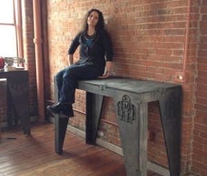
We had just moved into the MAKE Providence office and we needed furniture. I decided to create a set of standing-height plywood workbenches to house our 3D printers and other CNC machines. I have access to a large CNC router, and I wanted to design custom tables tailored to my measurements. And I prefer to stand when I’m wrenching on machines, rather than sitting in a desk chair.
So I used parametric, open design table configuration software to create a table to my personalized ergonomic dimensions. I then adjusted the files in a CAD program, programmed the toolpaths, and cut the plywood on a ShopBot CNC router. The plywood was then sanded and stained to give it the look of reclaimed, weathered wood, and then assembled by hand.
Depending on the tools and supplies on hand in your shop, you can build this CNC Maker Bench for as little as $100 unfinished, up to about $180 nicely finished. (That’s hundreds cheaper than MAKE’s traditional Maker Bench)
WHY A NEW MAKER BENCH?
If you’ve been to a Maker Faire, you’ve seen the , a sturdy workbench made from plywood, sheeting clips, and aluminum pipe. It’s extremely durable, but at ~$500 in materials, it’s expensive. Plus, it didn’t have the look of finished furniture that I wanted for our office. So I chose to CNC these tables based on cost, my ability to access the necessary machines, and the ability to create a custom design.
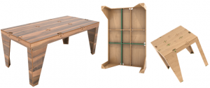
Enter AtFab’s Parametric Table
The “One to Several” table was created by award-winning architects , the creators of the CNC furniture line.
This table can be configured into many different variations by customizing the dimensions and joinery. has several parametric furniture configuration apps in progress, but they’re in Alpha and not yet available — until now
AtFab generously sent me the Processing version of their “One to Several” table to create the CNC Maker Bench and has allowed me to provide the app to MAKE readers so you can make one too
DOWNLOAD
The Parametric Processing App, CNC Maker Bench and ShopBot .CRV files are . You can configure your table from scratch or you can skip the app completely and mill my files.
from on .
Logistics
Machine Bed Size Requirements
Machine access is an important part of this project. You’ll need to use a CNC router to cut these files. A machine with a 4’×8′ (1,219.2mm × 2,438.4mm) bed is preferred, as plywood commonly comes in 4’×8′ sheets. The larger the sheet size, the easier it is to arrange the parts and less waste material is generated. However, you could make this design work with a 4’×6′ cutting area.
WHERE TO GET CNC ACCESS?
There are numerous shared workshops popping up all over the world where you can access a large CNC router. Check out our for more on how to get trained at a shop near you, so you can start busting out (almost) infinitely configurable furniture.
We want to see your table variations Send your photos, design files, tips, and experiences to anna (at) makermedia (dot) com.
LICENSE: In accordance with , the by is licensed under a . Permissions beyond the scope of this license may be available from .
Parts
- NECESSARY ITEMS
- Sandpaper, 80 and 100 grit (4)
- Work Gloves
- OPTIONAL ITEMS If you're going to stain your Maker Bench, you'll need most of these items,
- Varathane doesn't smell as much as Minwax.
- Pre-Stain Treatment, Minwax 1-Qt. Pre-Stain Wood Conditioner (1) Optional, I feel this helped with blotching.
- For wiping away the stain once applied.
- It's easier to apply stain to the semi-rough edges of the plywood with a stain pad.
- Your hands will get stained, wear gloves.
- Stain Brush I found the brush worked better with the stain pre-treatment and the pad worked better with the stain.
- Loctite Power Grab works well. You only need this if you have lots of gaps or want to permanently bond your Maker Benches together.
Tools
- CNC router, minimum 4'×6' cutting area 4'×8' preferred.
- Calipers, digital Important For measuring plywood thickness.
- I prefer an impact driver.
- You'll need the AtFab app in order to configure your own parametric table.
- The AtFab app was tested with Processing 2.1.1
- This is a dependency, the AtFab app needs this library to run.
- CAD Software You'll need to manipulate vectors and open and export DXF files.
- You'll need clamps if you use glue. They can also be handy for holding bowing plywood tightly together when you're putting in the screws. Get them cheap at Harbor Freight.
Advertisement
Advertisement
Advertisement
Steps
Advertisement
- The biggest factor to consider when designing customized standing-height tables is your individual measurements. Where do your arms rest when you’re standing? For good ergonomics, the table height should be at or just below your bent elbow height.
- I am 5'7", so a table 41" (1,042mm) tall is perfect for me, but you should measure yourself to see what’s right for you — after all, this design is parametric and completely customizable (with a little CAD work).
- To get a feel for how the benches would occupy space, I measured the bench width from the wall and marked the measurements with tape. I then marked off the area with more tape and took measurements.
- My version of this workbench stands 41" (1,042mm) high, but you might want to make yours taller. Check your wall to make sure any light switches or other fixtures will still be accessible.
- The MAKE Providence office has some funky wall features, with two pipes jutting out of the floor in the exact area I wanted to put two of the workbenches. I considered building custom tables to enclose the pipes. In the end, I decided that reconfigurability was important for our office. I created two workbenches that span the wall between the pipes, no custom cuts needed.
- To make one workbench, you’ll need two sheets of 4'×8' plywood. There will be some waste, but some of the material will be used for tests and you can use the scraps for another project.
- I chose Home Depot Pure Bond plywood. It has an attractive veneer and machines well with little delamination or tearout. I have had good results with the birch, red oak and poplar; but the poplar veneer is not quite as nice as the other two.
Don’t go for the cheaper stuff, or you’ll be disappointed with the end result. - Photos — from left to right — 4' x 8' plywood sheets:
- Why Plywood? Plywood has some advantages over other materials for this type of project, because it has a little give to it. If you make your joints a little too tight, or if your plywood thickness varies a lot, you can use a mallet to pound in the tight joints and the wood will give enough to accommodate it.
- Check for straight plywood. Regardless of where you purchase your plywood, take the time to look down the length of each sheet. If it’s warped, you’ll have trouble fitting your furniture together properly.
- Measure at the store. Measure the thickness of the plywood with digital calipers. If two sheets vary radically (by say, a full millimeter or more), choose sheets that are closer to the same dimensions.
- Pull from the same pallet. Natural materials have variation. If possible, get all your plywood from the same pallet. Thickness can differ dramatically from sheet to sheet, but will (probably) vary less within the same pallet. Also, the wood veneers will differ slightly between pallets; it will be more difficult to match the grain and the wood may not take stain or resist tearout on the router in the same way. (More on that later.)
- Avoid “voids” — places where the laminated wood has come apart and left a hole, especially on the top surface. Plywood of this type typically has an “A” side (nice surface, no knots) and a “B” side that’s acceptable, but not quite as nice. When the furniture is finished, you’ll only see one side, so cut it with the “A” side up. Make sure one side is attractive and don’t worry too much about the other side.
- Ask for help. I’ve found that most employees at stores like Home Depot and Lowe’s will be happy to help you sort through the stack and move pallets for you if you’re not finding plywood that’s straight or in good condition. Don't waste your money. Take the time to sort through the stack.
- Plywood has unreliable stated thickness. The tendency for hardwood plywood panels to vary in thickness from their stated dimension can be frustrating. If you buy a 3/4"-thick panel, for instance, it may stray 1/64" to 1/32" from that thickness.
- Measure each sheet again with digital calipers, checking the thickness at several points along its length and width. This is important for proper joint fit. There will be variations. Make a little chart and record your measurements.
- For example: on my first bench build the plywood measurements were:
- Sheet 1 ranged from: 17.5mm–17.8mm
- Sheet 2 ranged from: 18.3mm–18.5mm
- Download and install Processing. I tested the AtFab app with Processing version 2.1.1 — download from
- To run the app, you’ll also need the ControlP5 library, version 1.5.2 — download from the . Read the instructions on the homepage for where to put the libraries.
- Open the One to Several sketch in Processing. Since the diagrams were drawn for the magazine, the app has been updated, so the options have slightly different names.
- Enter your table dimension values into the AtFab parametric design app.
My values:- Width: 600mm
- Length: 1520mm
- Height: 1042mm
- Proportions: Free
- Sniglet Rows: 5.0
- Material Thickness: 18.5mm
- Fastener Holes: selected
- Fastener (Diameter): 5mm
- Options: not selected
- Export the vectors. Click the Save button and name your file in the box that pops up to export your custom design to a DXF file.
- Open the DXF file in your favorite CAD program. Lengthen the legs of the table to 41" (1,042mm) or your chosen length. The parametric app is awesome, but it doesn’t yet lengthen the table legs to standing height. You’ll need to adjust and rejoin the vectors manually.
- I drew a box around the table to the height dimension I was looking for, and then moved the feet vectors down to the bottom of the box. Then rejoined them accordingly.
- TIP: Anne Filson (of AtFab) recommended lengthening the legs by stretching only the upper portions of the legs, leaving the joints and feet intact.
- TIP: Lengthen one side leg and one front leg, then copy them.
- Possible pitfall — not moving the holes with the legs. Make sure to select and move the drill holes at the same time that you move the legs, otherwise, your holes will be in the incorrect locations.
- Ensure that each piece (or shape) to be cut out is formed by one continuous path. When you click on the shape in your CAD program, the entire shape should be highlighted. If you see discrete line segments, you must join the vectors together.
- Closed vectors are necessary for generating the machine toolpaths. If you’re using PartWorks or VCarve Pro for toolpath preparation you can utilize the excellent Join tools built into the software.
- If you haven't already, modify your canvas size to be the same size as your router bed. Then rearrange the parts to fit on your 4'×8' sheet of plywood.
- Set your canvas size to the units exported from the AtFab app. The AtFab app exports DXF files in mm by default, so to avoid any resizing issues: width 8' = 2438.4mm, height 4' = 1219.2mm.
- Create "machining margins." You’ll need to use screws to secure the wood to the bed of the machine (unless you have a vacuum hold-down system). Use an offset tool to create a box that provides 25.4mm (1") buffer around the edges of your sheet material. Otherwise, you could hit a screw and end up with a broken bit.
- There is some wasted space with this layout, you can use the excess to do your test cuts to verify the fit, or reuse the scrap for another job. If you’re cutting more than one table, utilize the extra space for additional crosspieces and feet — after making the test cuts.
- You can grab my final files from .
- The files were cut on a ShopBot PRS Standard equipped with a variable speed spindle.
- Here are the feeds and speeds I used for each tool size
1/4" Endmill (downcut):- Stepover: 0.125"
- Spindle Speed: 12000 rpm
- Feed Rate: 3.2 inches/sec
- Plunge Rate: 1.0 inches/sec
- Stepover: 0.125"
- Spindle Speed: 14000 rpm
- Feed Rate: 3.27 inches/sec
- Plunge Rate: 1.1 inches/sec
- Tooling. I used a downcut or “downspiral” bit for the profile cuts.
These downcut bits force the chips down into the bed, packing around the cut piece as it's being cut to hold it in place. I cut all my wooden parts this way; it reduces the need for cutting off "tabs." Tabs are design elements created to hold the parts in place for cutting. - Chip load. This is the amount of material removed with each rotation of the bit. The smaller the bit, the less material it can remove with each pass. The tool manufacturer Onsrud is .
- Feeds and speeds. Feeds and speeds are determined by a mathematical formula to give you basic safe settings for the bit used and material cut. As you gain experience you can push the tool harder to reduce cutting time. You want to move the tool as fast as the “chip load” for your bit will allow, without breaking your bit or sacrificing finish quality, as heat will build up and can catch fire if you move the tool too slowly.
- How to calculate (roughly):
- Chip load: ~ 0.001"–0.010" feed rate (inches per minute) / (RPM x number of flutes)
- Cut depth: ~ tool diameter
- Step-over: ~ tool diameter/2
- Plan your toolpaths. If you’re drilling the holes (as I did), and adding a decorative image etched into the surface of the wood (like the MAKE robot in this project), you’ll need to create additional toolpaths for each operation. Depending on the size of the image you're engraving, you'll probably need to use a smaller tool than you'll use for the through-cuts.
- Note that there are two different types of toolpaths for this project:
- Inside Cuts — the “cross” or “plus” notches on the tabletop.
- Outside Cuts for the rest of the file.
- Unless you plan to glue your table together without dowels or screws, make sure you drill marking / clearance holes. I drilled 6.5mm (1/4") screw clearance holes.
- Toolpaths must be cut in the proper order: first etching or “pocketing,” then drilling, inside cuts, and finally, outside cuts. (You don’t want to cut out a part and then attempt to drill or etch the loose part)
- Preview your toolpaths in your CAM software.
- Generate and save your toolpaths in the appropriate file format for your machine.
- If you are using PartWorks, follow .
- Cut your test cut toolpaths, and slot your test pieces together. According to AtFab, you should be able to fit 1–3 business cards through the joints when they’re slotted together. You may need to adjust or rescale your file to get your parts to fit together properly. For more details, see the
- My joints were very tight and I had to use a mallet to knock them into place, but they worked just fine.
- Once you’re satisfied with your test fits, you’re ready to cut your files. This is the fun part. Go, ShopBot, go
- Set up your machine, put the appropriate bit in the collet, and run your toolpaths in the correct cutting order.
- Safety first Remember to wear eye and ear protection.
- About tearout. Sometimes plywood can “tear out” or splinter along the edge of the cutting tool, typically where the tool exits the wood, on the bottom of through-cuts (with a downcut bit). Using sharp tools will help to minimize tearout. I had radically different tearout from pallet to pallet of wood, so keep that in mind.
- For this project, we don’t need to worry much about tearout on the bottom of our cuts because they’ll be hidden. But be aware that plywood from different pallets can tear out completely differently when you rout it.
- You’ll also have some tooling marks from the router, sand them away or leave them, it’s up to you.
- I used 80 grit sandpaper to sand off rough edges on the bottom side of the cut parts, caused by minor tearout from the downspiral bit. The front edges were perfectly clean.
- I used 80 and 150 grit sandpaper to smooth out the pocket-cut robots and the top surface where needed.
- TIP: Use a foot piece as a sanding block. Wrap the sandpaper around the block and sand away, it will make your job much easier.
- Use a tack cloth to remove fine wood particles after sanding and prior to staining.
- Test your stain on a scrap piece from each sheet before applying it to the finished pieces. Different plywoods take stain differently and you want to make sure you love it before you commit to it. Oil-based stains are messy — use a tarp.
- Use stain pretreater to get a more even stain application.
- Wipe on the ebony stain with a stain application pad and then wipe away after a few minutes while still wet for a dark, weathered look with visible grain.
- TIP: Oil-based stain stinks. Ventilate your space well. If at all possible, stain outside and let the wood air out as long as possible. If indoors, light some candles to the burn off the fumes. Some other folk remedies include a bucket of water with vinegar and cotton balls soaked in almond extract to help adsorb the smell.
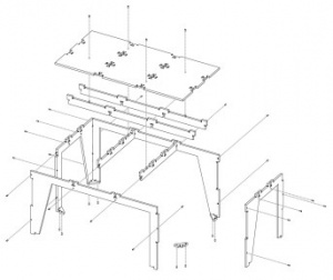
Assemble the workbench in this order, or it won’t fit together properly and you’ll get frustrated.
- Crosspieces.
- Back into Crosspieces.
- One Side piece
- Front.
- Other Side piece
- Top must go last — see next step
- If the joints are a little too tight, give them some encouragement with a mallet and the plywood will give.
- Add the table top last. It will probably require some pounding into place with the mallet. Wrap it in a rag first to avoid abrasions.
- Drill countersink holes. If your screw heads are too big to fit inside the 1/4" drill holes, chuck a 5/16" bit into your drill to countersink them. If the screws fit, don't bother.
- Screw the legs, feet and top into place. I strongly recommend using screws. You can add glue to help fill looser joints; if you do, clamp them well and let dry.
- TIP: Mark your drill bit with a piece of tape so you don’t go deeper than you need to.
I showed you mine, you show me yours. Send your derivatives, tips, and experiences to anna (at) makermedia (dot) com.
It's addictive, you'll want to make more than one. I've made four Maker Benches so far. ;-)
Anna Kaziunas France is interested practical digital fabrication focused project documentation (anything that turns codes into things), as well as adventures in synthetic biology, biohacking, personal genomics and programmable materials.
She's currently working on the forthcoming book "Design for CNC: Practical Joinery Techniques, Projects, and Tips for CNC-routed Furniture".
She’s also the Academic Dean of the global Fab Academy program, the co-author of Getting Started with MakerBot and compiled the Make: 3D Printing book.
Formerly, she worked as an editor for Make: Books, was digital fabrication editor and skill builder section editor for Make: Magazine, and directed Make:'s 2015 and 2014 3D Printer Shootout testing events.
She likes things that are computer-controlled, parametric, and open— preferably all three.
Advertisement
+ General Reviews